|
|
Post by roger on Mar 3, 2019 0:58:05 GMT -5
This build started in Jan 2017. It is condensed down from 25 pages. It is now open to read and comment on.
PAGE 1
I have held off posting my TR1KE build until now. I took delivery of my RTR built kit this past October. For ease and economy of shipping the dealer arranged it as a rolling chassis with some of the aspects of a normal build completed. Trust me, there was plenty of work to do once it arrived. It is from this platform that I choose the beginning of this thread.... simply continuing the build initiated by the seller and his associate. For those that may ask, this kit is considered NOS "New Old Stock" and carries a Manufactures Certificate of Origin dated October 2013. Road Track Race was in business from 2009 - 2015. It is solidly an RTR product when imported to the USA. I also am the owner and builder of an MEV Eco-Exo-R. It was the 1st one on the road in the USA, and it is quite fun to drive. That being said, I need to press forward and do some photo posts and bring this TR1ke thread up to speed. It is my aim to start the updates in the coming days.... give me a few days to arrange my photo bucket account and upload some pictures to post here on the forum . Best regards to all.. Roger Worcester, Massachusetts
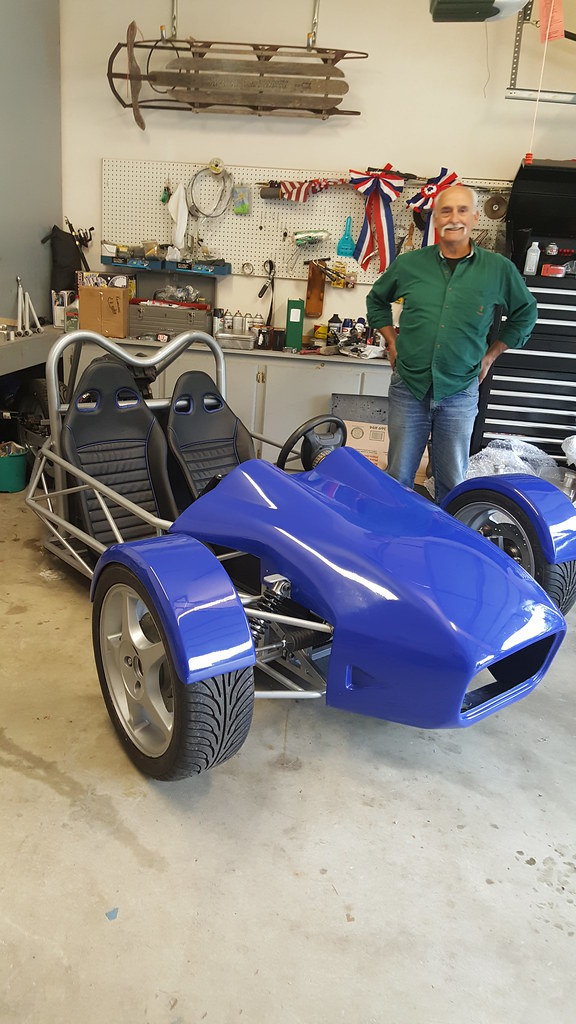 After receiving TR1KE from the dealer and getting the protective layer of cardboard removed this is what it looks like. My friend Allen, was of great assistance in this process. The fenders were placed atop the tires for this photo.
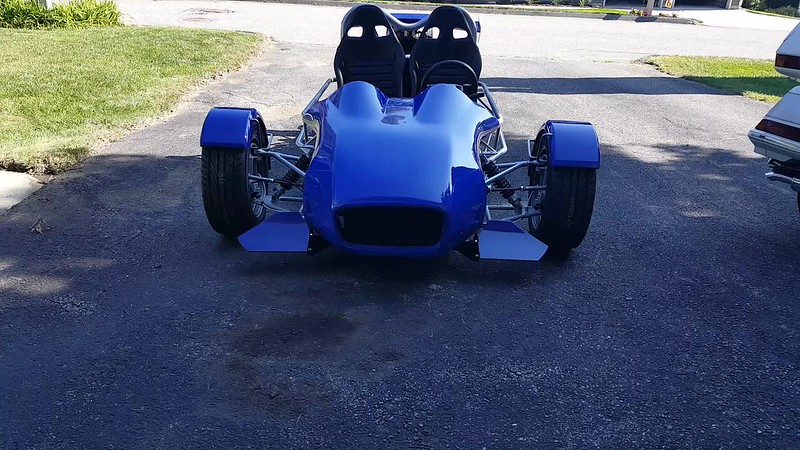
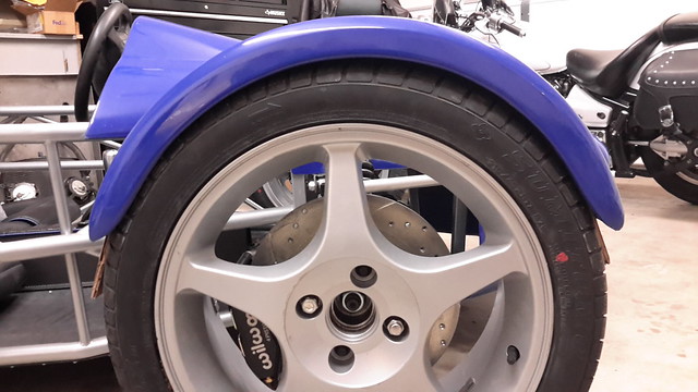 The kit was shipped with the Ford Focus SVT wheels and tires. I found these 17 inch X 8 inch bruisers to be oversized for the look of TR1ke. The front fenders looked awkward and did not follow the contour of the tire once properly spaced so I had to purchase something that would not only fit, but allowed the fender to follow the round contour of the tire... 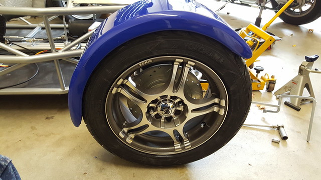 I selected a 15 inch X 7 inch wheel. There was sufficient clearance inside for the Wilwood brake calipers and for tape on balance weights. The fender follows the contour of the tire with ample clearance. Yes, it is snug, but nothing rubs. I measured 1/2" of clearance. Now, I need to sell the mounted Sumitomo tires and SVT wheels.
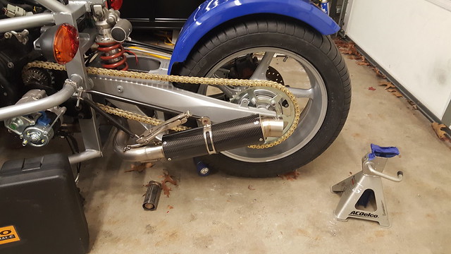 The dealer sent up the stock 2005 R1 mufflers, however after examining all the modifications needed and having to weld titanium my thought process changed to aftermarket mufflers. These are carbon fiber wrapped Danmoto mufflers. I ordered the optional baffles to bring the exhaust down to a mellow tone. DanMoto markets these as direct replacements for OEM. When I ordered the TR1KE kit, I also purchased the optional exhaust "Y" pipe. The Danmoto mufflers were nearly a perfect fit. It cost me $10.00 to have the "Y" pipe exit ends expanded to fit into them. I was considering a Leo Vincent system, but the price was prohibitive. I made two support brackets for each side. One to support the muffler, the other to support the "Y" pipe. I ordered 2 chrome handle bar clamps last year and never used them. The clamps provide the support to the frame. The supports are rock solid and secures the entire system. The "Y" pipe is stainless steel and is excellent quality. If you have a TR1KE and want to install dual exhaust, this is the ideal solution. This photo was taken during the design phase of my build. So excuse the vise grips.. 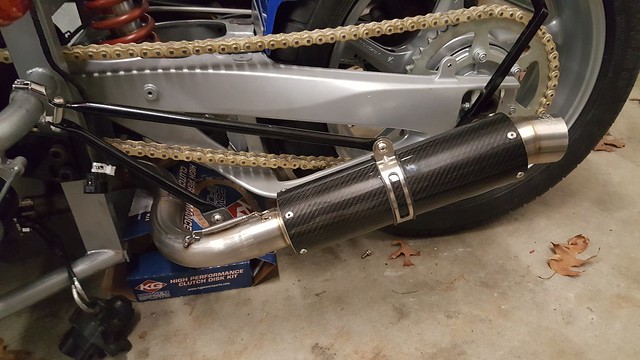 Completed exhaust installation with stainless hardware......and supports were powder coated. As you may notice, the clutch kit beneath the trike is an indicator of where I was and what I was doing a week or two ago. Roger Worcester, Massachusetts
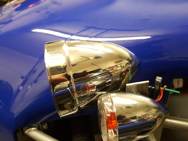 I bought the Adjure Headlights. I found a nice matching (or close enough) pair of turn signals as well. The chrome touches I am adding will be kept to a minimum. The headlights came with both LED and halogen electrics. I opted to keep the halogen. After speaking with the folks at Adjure I am confident the Halogen bulbs will provide ample lighting. Since I am using incandescent bulbs in my tail and brake lights, all other lighting will be incandescent as well. The excess flat stock I used to manufacture the turn signal mount will be trimmed and shaped before powder coating... Well, so far so good...... Roger Worcester, Massachusetts |
|
|
|
Post by roger on Mar 3, 2019 1:04:43 GMT -5
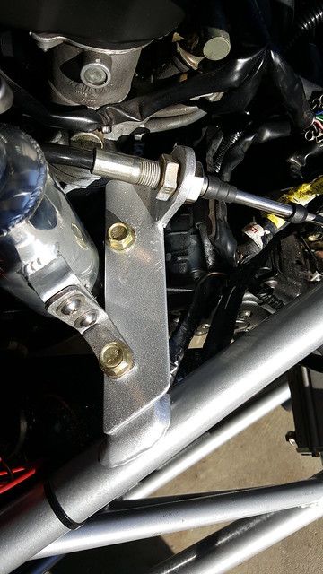
 These mechanical parking brakes calipers are not really suited for anything more than to hold the Trike on a gradual incline. When I received this already attached, the brake disk pads would not fully engage the rotor. I would say about half the pad was hanging over the outer edge of the rotor and was completely ornamental and not functional. I milled the inside "nose" down about 3/4". The brake pads now fully engage the rotor. For what it is, it will have to work for now. I am working on modifying a Suzuki Burgman rear caliper. They are both hydraulic and mechanical. This caliper might be better suited to something like a Go-Cart. 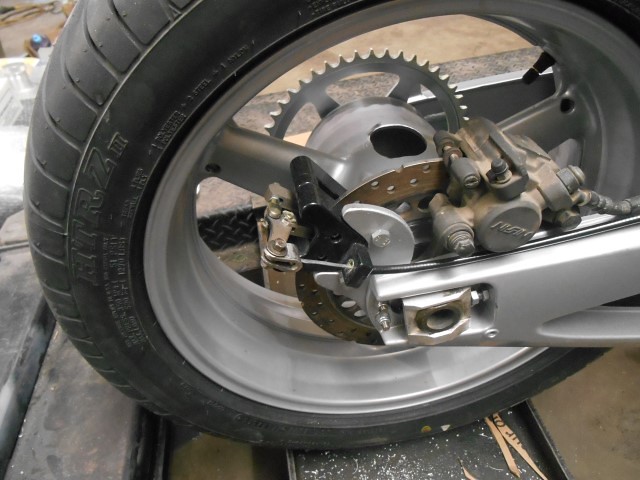 The caliper came mounted on this adapter. It wasn't a bad idea, it was nicely made and sturdy...... but..... if I needed to adjust my chain the caliper would not move with the rear wheel. The fit is VERY CLOSE and any wheel adjustment could cause the caliper to contact the center hub. 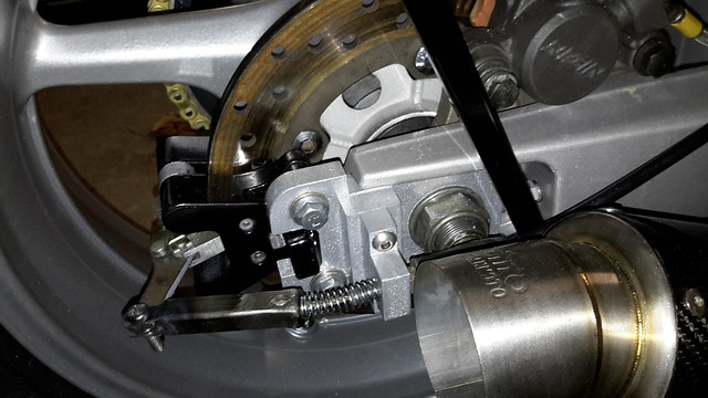 I found this mount and decided it was a stroke of genius. I "borrowed"... Okay... Shamelessly nicked the pattern and adapted to my modified caliper. It serves as the spacer and adjuster hard point. It is thicker than the original I patterned this after and the entire system moves with the rear wheel when adjusting the chain tension. My hat is off to the original designer.... Roger Worcester, Massachusetts  After buying a Momo (counterfeit) adapter and having absolutely no luck making it fit, I returned it and made my own. I used the OEM Ford Focus steering wheel. I cut the center out of it and milled it to fit an extension made from a piece of 2-1/2" aluminum round stock tubing with a 3/8" wall. By the way, the Ford hub is white metal. It will NOT weld like aluminum. The quick disconnect adapter was easy enough to fit. My lathe indexing wheel made it a no brainer. 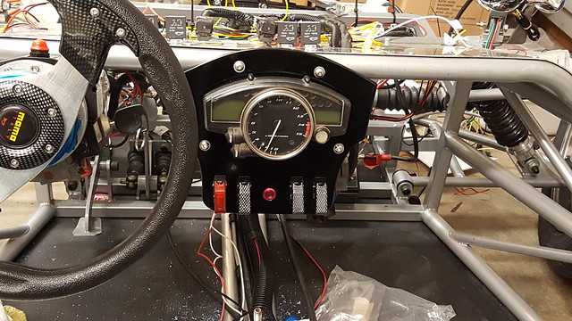 I mounted the "clocks" on a 1/4" thick piece of aluminum and had it powder coated. The switches are for Run/Stop and the Red one is for a safety when using reverse. The red switch is provided a ground from the neutral switch and when toggled passes the ground on to a button on top of the gear selector. So, in order to use the electric reverse, you need to place the gear selector to neutral, toggle the red switch then depress the button on the gear selector. The other two switches are for future consideration such as driving lights and for the optional camera mount power. The key point about the way everything is mounted on the aluminum is this allows easy removal of the bonnet. The entire piece is hinged at the bottom and will swing rearward once the two mount screws are removed. The speedometer plug doesn't need to be touched. The entire assembly is quite sturdy. Below is a mock up of it mounted with the bonnet attached.  There are more photos coming. It is my intent to provide an overview of the work so far. Even though the kit came as a rolling chassis, that only means it can be pushed off the delivery truck and into my garage. A lot of the assembly to make it a roller was not suitable as a permanent assembly. It required some re-work and proper hardware to be safe. I needed to address the steering column installation and do some welding on the attach points. I also needed to order the steering rack extensions. These must be a hard item to get. I asked the dealer to order from his source around 6 - 7 weeks ago and nothing yet. I finally ordered the 14mm X 2 tap and some hard roll stock and made my own. When I contact the dealer he has been very proactive in obtaining parts and items needed for the completion of my project. In the initial order I purchased a good deal of accessories. Upholstered seats and console instead of the standard seats and bare aluminum console. The upholstery is first quality or better. It is going to add to the comfort and design of the entire TR1ke. I would highly recommend this option. The dealer installed the shifter and cable as well as the parking brake assembly. Both needed tweaking, the shifter cable required a better mount at the engine, and I already covered the issue I had with the parking brake. Other accessories included the custom exhaust "Y" pipe and electric reverse. Two thumbs up on both of these. The "y" pipe is stainless and is custom made for the TR1KE that is designed for the 2004 and newer R1 donor. Reverse naturally speaks for itself.... The dealer went out of his way to offer powder coating on the swing arm and front and rear wheels. Naturally there is a cost associated with all of the services and options, but they needed to be done and the color continuity remains consistent. In retrospect I should have waited to do powder coating at my local business, and taken advantage of a package deal. As it is, the front wheels (and tires) were replaced as well as the rear wheel. The front wheel and tires would have "worked" but the fenders just looked to small when placed over the tires. As for the rear wheel, it turned out to be an older 3 spoke R1 and was missing internal parts. The 3 spoke wheels are married to the older 150 HP R1 engine. The 2005 engine in my kit is 180 HP. I had very serious concerns about it being able to withstand the 30 extra horsepower and the extra weight. The dealer shared this concern as well and generously replaced the wheel with a 2005 R1 spec wheel and included powder coating and shipping. In the end, I am very pleased with what I bought. Yes there were some areas that needed to be addressed and they were taken care of either by me or the dealer (Dove Racing LLC). The chassis construction was/is superior. The welds, materials, accuracy is all professionally done. Whoever was responsible for chassis assembly in RTR had his s--- together. There is much more to do and I have the winter to do it. I have slowed down a bit in order to spend some time inside. Roger Worcester, Massachusetts 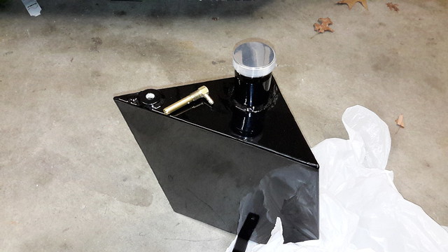 I had an unfortunate incident with this fuel tank the powder coater left the cap on to bake the powder. The silica media melted and glued the cap to the filler neck. I bought a Chinese assembly on ebay and had it repaired and recoated. I also had a fabrication shop remove the vent stems and install 1/8" NPS threads for the approved roll-over safety vent. All three tanks were modified. I would recommend to the factory to do away with the open vent and install the roll overs. Roger Worcester, Massachusetts |
|
|
|
Post by roger on Mar 3, 2019 1:09:54 GMT -5
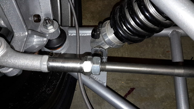 The home made steering rack extension right and left 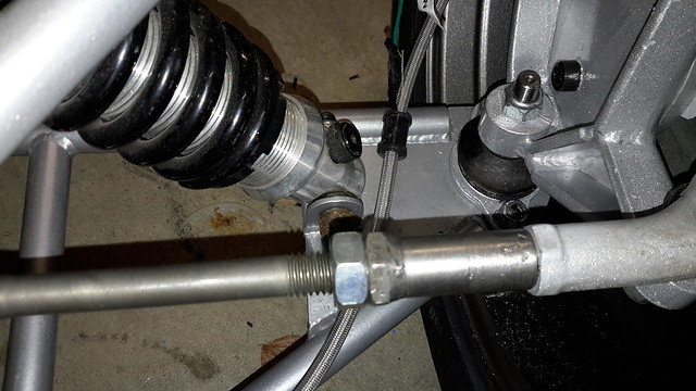  Fender mount on hub. I used 13mm nuts and bolts. The GRP fender was adhered to the frame with windshield adhesive. This stuff will glue water together. I ordered stainless steel brake lines from HEL. They are fantastic company and are willing to work with you on anything that needs brake lines. Hidden inside the Konig wheel is the Wilwood Caliper. 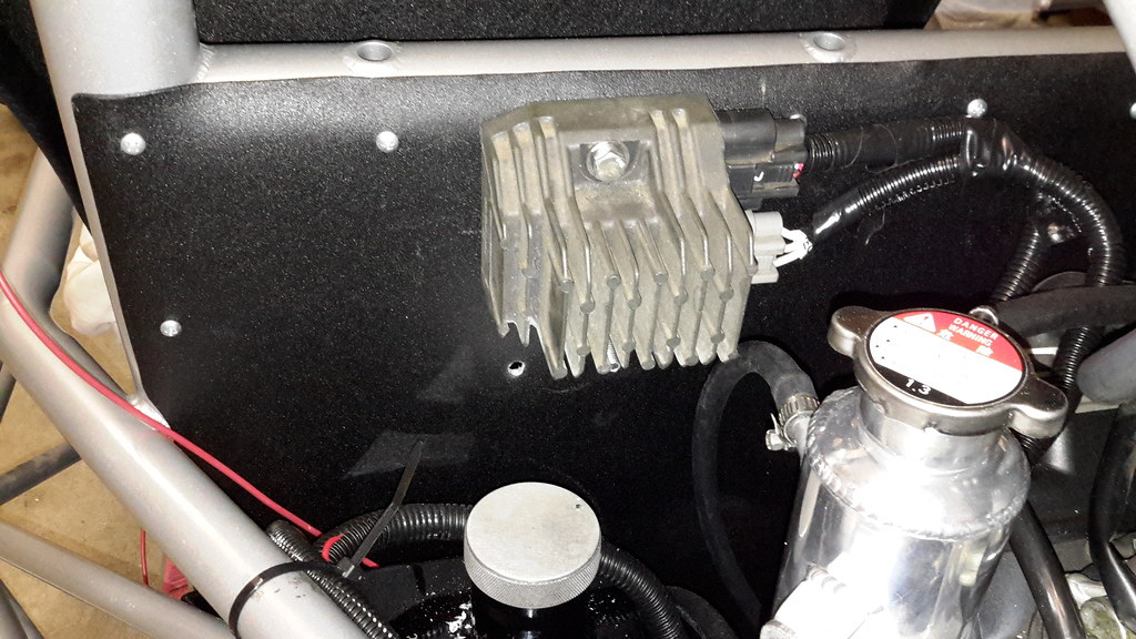 I mounted the rectifier on the rear left bulkhead. The small hole in the bulkhead is for securing the wire loom seen in the photo. Below that is the "Carbing tank". Since my radiator is lower that the engine, it seems necessary to install the tank. 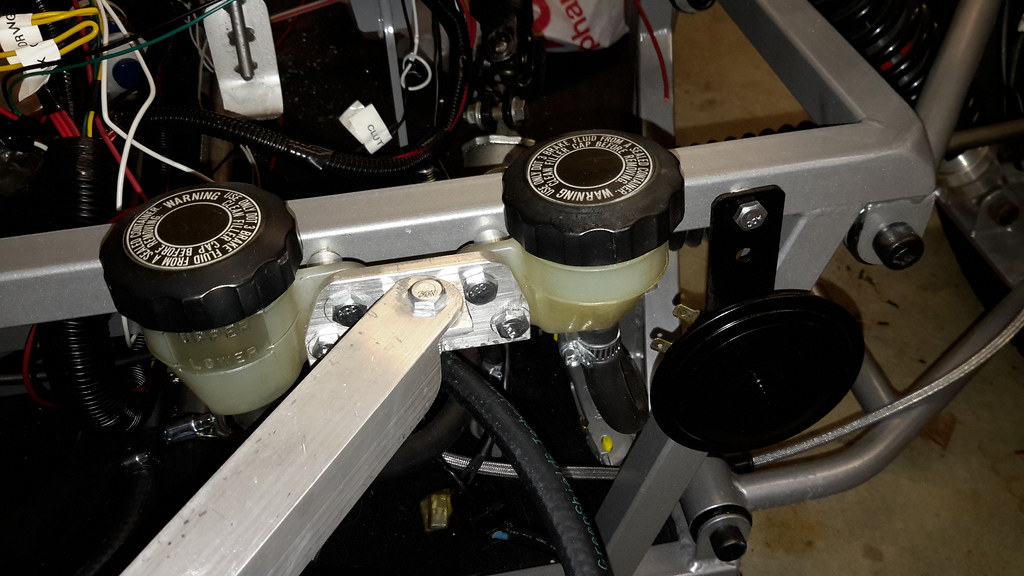 I used Honda GL1100 rear brake reservoirs for the front and rear brakes. The master cylinders were fitted with AN fittings and barbed connectors to the reservoirs. The aluminum brace in the photo is for the radiator. 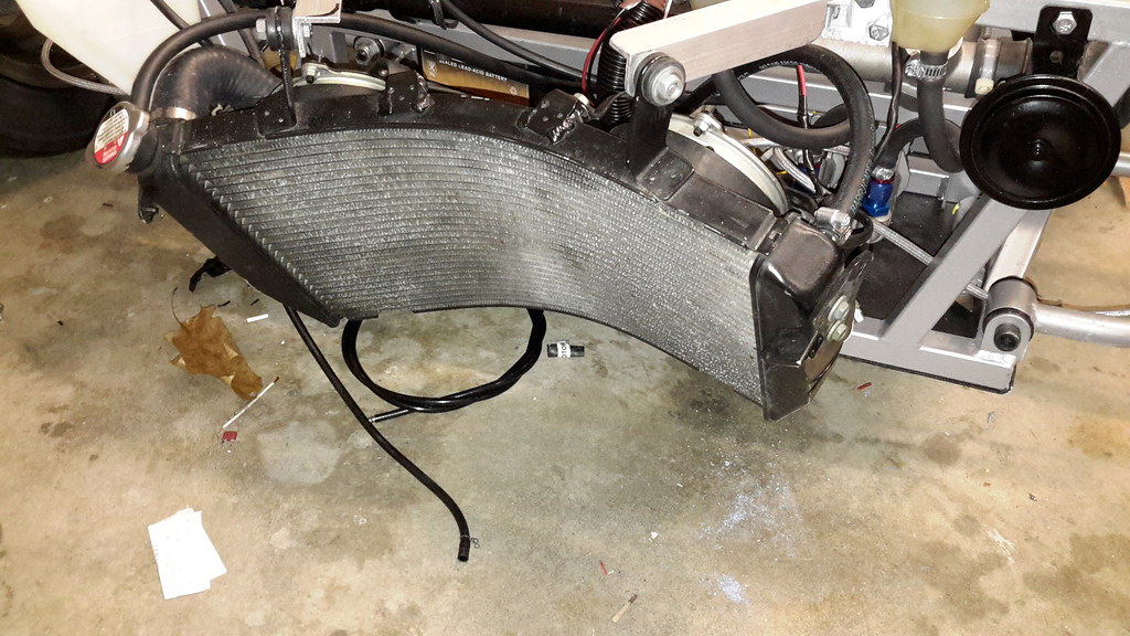 The radiator was easy enough to install. All hoses are connected and system is ready to be filled. I have held off doing that just in case I need to remove the lines or open the system....... |
|
|
|
Post by roger on Mar 3, 2019 1:18:47 GMT -5
PAGE 2 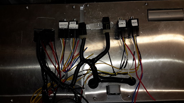 I still need to wrap the wiring harness and install a few strain relief fittings. I will not do this until I do the total wring out and electrical installation and make sure EVERYTHING works as it should. I do NOT need the worry of slicing open the harness to troubleshoot or chase sparks.... Roger Worcester, Massachusetts  I made the rear fender braces and had them powder coated. I am actively working in this area. The front support still needs to be coated, but will gather up the rest of the bits and pieces that need coating before heading over to get the bracket done. I cut the fender down in the rear and cut a passage notch so the chain guard will fit. 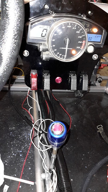 The extension to the main harness went well. The instruments all work, the lights light up and all the bells and whistles perform their respective functions. Note the push button on the gear selector. That is the reverse button. As with most builds, organized chaos is the organizational discipline of the day. In the end, the wiring will all be trimmed and wrapped. The floor pan will be washed and cleaned and all smudges, scuffs, scrapes will ALL BE taken care of. Initial start on starting fluid. Just a quick blast... I took a little time and cleaned up my work area this afternoon. I also took a few pictures with the bonnet and console installed. I will be doing a lot of catch up with my progress in the coming few weeks. 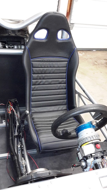 Nice upholstered seat. The seat bottom is installed with velcro so it makes it very easy to bolt to the mounts |
|
|
|
Post by roger on Mar 3, 2019 1:36:00 GMT -5
 As mentioned in a previous post, this is the engine end of the shift cable. I replaced the original dealer installed bracket with this one. 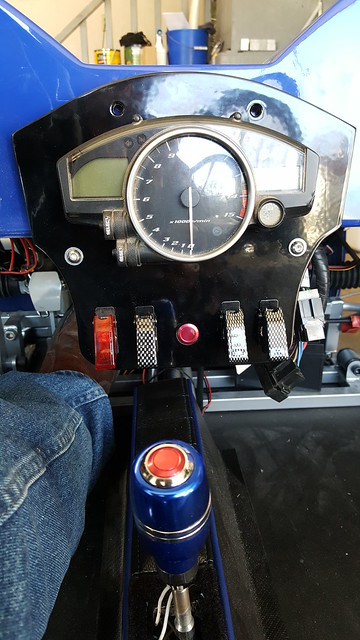 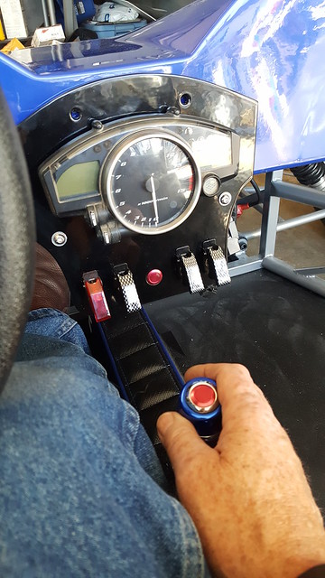 The ergonomics of the instrument cluster and gear selector are not bad. I am 6' and there is plenty of room. 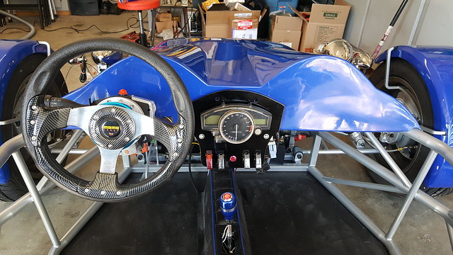 The instrument cluster along with the bonnet. I have found the bonnet hides a lot of sins....  I found the tank on ebay. For this purpose the tank connects a "rat race" circuit between the radiator return and the thermostat bypass. It also is the means to top off the system after the radiator in the front is full. The overflow tank is also connected to this device This is the plumbing diagram associated with this tank... |
|
|
|
Post by roger on Mar 3, 2019 1:46:34 GMT -5
 Getting ideas for the huge opening in front. The mesh stainless is always good but was thinking of installing small driving lights with a connecting bar between the two. Maybe three horizontal bars to decorate the fish-mouth. I still have time to think about it. Well Roger, another fine job. I will be following this build too. I am following you're build too. If i would not have a sonic to build i would really consider a tr1ke because i like the concept, normally i don't comment a lot in the forum because i probably know less than the most builders here, but when i read you're post in the eco exo thread you seemed a little bit disappointed that it was slow and no one was reading, so i wanted to let you know there are interested people here, so keep on posting.  Hello Dave... it's going well. Need to stick close inside. Wife JUST home from surgery. Will suspend work during her recovery. Should be a few weeks... or less. Roger.. Really coming along.. One thing your front tire are on the wrong sides switch them L > R so the "V" is going forward not aft. The way they are now it will force water under the tire not outward.. I really appreciate the comments Kevin, but I am not disappointed. I know, for me to qualify as a builder on the MEV Proboard I had to build a TR1KE kit manufactured by "Road Track Race" and not "Exo Sports Cars". The RTR kits are few and far between and I would probably be the only active builder. I know the build is being viewed because the "View" counter has about 250 hits. About a third are from me posting and editing. No comments are necessary. I was hoping the guys that already did a build would chime in eventually and keep me on track. It is fun and challenging to build a kit car (trike) and when you have like minded guys sharing information it makes the build a group effort and everyone shares in the success of it. The Eco-Exo section is special to me. Between Erik, Eddie, Fred and me, we kept that section quite active. The Eco-Exo was quite fun to build, journal and share with everyone. There were parts of the build that Erik solved for me as well as Eddie. When Fred in Pennsylvania started his, we all helped him. There just isn't anyone building a TR1KE except me. The forum is a great place to journal. Access is worldwide (except China and N Korea). No matter where I go, I can refer to my entries on any computer. I have met folks on here that I know I will not meet in person unless there is a huge kit car meet here in the USA. THANK YOU for following the build. If you have questions I would be more than happy to answer. If you see me making a monumental blunder... by all means call me out on it. I would rather be corrected than continue down the wrong path. With that, I must say I am happy to post, and build an MEV TR1ke. Roger Worcester, Massachusetts |
|
|
|
Post by roger on Mar 4, 2019 0:24:08 GMT -5
PAGE 3  I actually caught that about 2 minutes after I took that picture in December. This photo was JUST taken....:-) I thought the radiator was a little looking strange myself. It looks like it had an unfortunate encounter with a tree or power pole. It is actually an OEM stock radiator from a 2005 Yamaha YZF R1. No trickery, no magic just 100% pure Yamaha weird engineering. Its one of those engineering wonders that makes no sense till you understand it was curved around the front tire for clearance. Are you going to do a bypass flapper door to direct some heat into the cockpit? Dave, once I get all of the components in place and secured I will install a small split duct from the radiator to each side of the center console. The main radiator exhaust will be in and around the A arm attach points. I will go to the breakers yard to see if I can find a vent flapper. I will probably have to use some pretty creative design work to do this but, riding in this area requires a little help when it comes to spring and fall riding. Having auxiliary heat would come in handy. Roger Worcester, Massachusetts Roger could you use something like this hot rod heater on ebay only 9"x10"x5" ebay # 121857535643 make up a T fitting for rad in/out hose. And maybe for the cold season make up some removable side plastic panels for the front half of the cockpit.. The heater is a good idea. That unit is quite compact and could probably throw out a lot of heat on a cold day. My plans call for installing some smoke charcoal colored acrylic panels along the bottom edge of the chassis. I installed painted aluminum panels on my Eco-Exo and they REALLY" keep out the cold. What I have concerns about on the TR1KE is the waste heat from the radiator and dual fans. I have not seen anyone mention this in their builds. (The information might be there, I just have not seen it) I realize there will be heat pouring in, but I am not sure if the mix of ambient air moving through the trike will dilute the waste heat enough to be comfortable. I am in the thought process of installing diverinary panels to have all heat exit the trike either out the sides or bottom. Roger Worcester, Massachusetts |
|
|
|
Post by roger on Mar 4, 2019 0:35:49 GMT -5
Heat in the cockpit is nice when its cold out. But on a 85 Deg F day, uh NO. Engine heat from the radiator can kill you quick on a hot day. I do not think it will dilute enough. It must be 100% ducted out, ether under or to the side. Even blowing over the wind screen will roast you on a hot day. I am in the process of trying to figure out where to vent the waste heat to. More likely out the sides. It isn't necessary to get anything installed just yet. Certainly not for the "BIG inspection. The passenger side will be easy, the driver side will be a little more difficult. I am waiting for a TR1KE owner to add some information on this topic. Roger Worcester, Massachusetts Roger you know I did the downdraft method on my trike and did it like an aircraft cooling system. It has worked extremely well and the radiator temp is spot on in the center and never moves no matter what the temp is outside. This prevents any air from the radiator or radiator opening from hitting my feet keeping me warm on the colder days and cool in the summer. I did see some earlier Tr1ke posts on this subject and more on the hot side in the Summer time. I am sure you will come up with the best solution for the problem. You always have heated pants and jacket if needed when it gets real cold:) I like to keep it simple myself. Edward I would like to get this bit of engineering put behind me. It is something I know I will need to address. Without making major changes to what is already in place, something as simple as ducting the waste air through the bottom of the floor pan may be the easiest solution. What I am in the process of doing right now is working on completing the details behind the engine bulkhead. Getting the tanks fitted, installing the fender and securing the wiring, hooking up the reverse system, and routing the fuel lines. I have enough room in the front to route and vent the radiator heat. The question of just where to vent it is still something I need to consider. I like your statement of keeping it simple Eddie...... It will be simple, and probably prototyped in coroplast...just like my air scoop on the Eco-Exo-R. I will let everyone know how I plan to proceed on venting the heat.... just as soon as I know myself...:-) Roger Worcester, Massachusetts I did a little wiring today and have the reverse switch wired and connected to the reverse motor. The wiring is a little rough looking, but just needs to be trimmed and placed inside a loom. Good work Sir. I would suggest you consider an anti roll bar, trikes do suffer from excess body roll and stiff springs to resist roll makes them less compliant. One guy who was one here tried an ARB but the bends in it were way too far from the mounts so it was not going to work. Not sure what strength you need but try an MX5 rear. With mods to the bends (cherry red) it could be just the ticket. There are on track videos online somewhere and pictures showing body roll on a tR1ke that creates excessive front camber gain and reduction in rear contact patch/traction. Once the mass shifts to one side the inevitable is not far away. The TR1KE isn't going to be used as a track vehicle. Once I get it legally registered and on the road I plan to do some handling tests. I know I had some handling issues with the Eco-Exo-R when I installed progressive front shocks. I went back to the stock shocks which are quite stiff. I have no problems with the handling and have not revisited the experiment with a softer ride. The TR1ke has some pretty beefy front shocks installed from the manufacturer. I also installed an aftermarket heavier coil over for the rear shock. I am aware the rear tire keeps perpendicular with the frame during a chassis roll situation causing the potential of uneven tread contact from tire to road surface. I have seen videos of motorcycles equipped with car tires installed (referred to as Darksiding). The tire is actually quite pliable and the entire tread keeps contact with the road surface except in deep low angle turns. I am counting on a few degrees of chassis roll, but not enough to lose traction because of tread contact, but with 180 Horses in the engine, it is enough power to break traction during straight and level jackrabbit acceleration senerios. (aka: doing hole shots) so.... it is worth considering. When it comes to adding an Anti-roll bar you can bet it will be installed should I find myself in a situation where handling is compromised with normal road driving. I will finish my "normal build, run it through the inspection process, get it insured and on the road, then do some additional handling tests. The installation of an anti-roll bar shouldn't be major engineering, but will need to designed into the overall chassis for proper fitment. Thanks for the suggestion. Roger Worcester, Massachusetts picture taken at road speeds without ARB.  |
|
|
|
Post by roger on Mar 4, 2019 0:55:39 GMT -5
PAGE 4 I can see where the rear tire is lifting on the off side of the tread. The chassis roll out is quite pronounced as the driver lays into the corner. The MX-5 anti roll bar installation will be in the back of my mind as I proceed with the TR1ke project. I can also see where the aid of a good blacksmith might come in handy to have one custom built. Thank you very much for the photo and for posting on my build. This is the sort of feedback I really appreciate. Roger Worcester, Massachusetts That pic was taken with stock linear springs which are known to be weak. Progressive springs keep the chassis near level when cornering because they get stiff when pushed. For this reason ARB doesn't make sense to progressive (calculated and matched to suit the vehicle) because ARB is just as dumb linear axial counter acting torque spring as dumb as a linear wound spring it only affects a progressive spring on the negative side. Progressive wound springs do not need pre load (tension nut in it's loosest position) to serve to it's full calculated characteristic. Any pre tension on a spring is a restriction on it's characteristic. My spring engineer was very keen to drive my tR1ke on track for testing only the value of the beast was too high to risk damage on a track day. He is a car and motorcycle track instructor as well which is one of the few around I thrust sitting next to  . Your radiator position is very likely to overheat in summer there have been many reports over here of overheating both flat rad and bend rad. You need to spend every effort to cool your drive system and exhaust pipes which is priorty #1 or your engine will break down or you need cooling down sessions. Because of this I'd highly recommend not to add a waste heat vent system tunnels unless you are 100% sure the heat will be sucked through the radiator when driving and in queue or at stoplights. Cooling fans have more trouble pushing the air through a vent as without one. For this reason I did not use a firewall in my Exo and made quite some mods on the tR1ke. The tR1ke is 100% thermal proof the fan did not turn on on 30Celcius. Oil temp is quite hard to push past 100celcius in urban environment and highway Hot air from the vent is not an uncomfortable feeling to the lower torso when driving on the hottest day. On cold days it does prevent your lower torso from freezing tough your upper torso gets very cold. Don't mind the hot air under the bonnet the airflow does get widened and mixed with cooler air makes it only warm. NOT very warm just warm. Never had overheated feet. As I mentioned in both my threads, The brake fluid reservoirs need to be in plain sight to see you are running out of brake fluid or you need to install a brake fluid level indicator switch and dash light switch appropriate warning symbol. If this is not, you will fail European legislation rules. It is a safety feature which makes sense for your own personal safety. The brake fluid hose on your reservoir need to be approved for brake fluid as well take care you have this well documentation. double secure the hose both ends with T-wraps (2 at each end). Make sure the brake lines on the brake caliper are routed properly to have a full bend and torsion free movement when turning the steering wheel to it's limits. This is a very weak point at many kit cars which basically should tear open your brake line at the caliper side fitting. I managed to do this with braided stainless steel brake lines on both my trikes. to check the torsion on the fittings have the brake lines not attached to the + fitting in center of your car. rotate the steering wheel and watch if the fittings on the brake lines do rotate. if they don't your brake lines are stress free. Nice build! greets! Erik Forgot to note that pic was taken with the original A-arms they had been modified on later versions. I noticed Rogers tR1ke has standard springs, delighted to hear you have made some handling improvements Erik. I cannot tell from the picture I posted if the car has progressive springs or the longer bones as we cannot see them. It would be good for all trike builders if you posted the spec of your chosen springs. All coil springs get harder as they compress. They are rated at X lbs per inch of compression. The progressive ones you mention will have coils closer together at one end to keep the ride softer at the start of compression. This rate increases on a different scale to ordinary springs but can result in very stiff suspension on the limit. Interesting stuff but maybe this should be in the tech section instead of filling Rogers blog. The build of my tr1ke has been thoroughly documented in my thread and it's easy to see the modifications I made because I try to post details and data previous builders have overseen which is my pocket change after reading their threads . I guess it's worth reading instead of serving it on a silver plate. The only thing which lacks on my tread is a picture of proof the progressive spring is at it's loosest length. In this link you can see the progressive spring during the build (they have been purchased based on Edwin's experiences on these springs but he had the older A-arms on his version .My springs have been changed later after the tR1ke has been approved road worthy. mevowners.proboards.com/thread/2141/tr1ke-build-netherlands-erik-4?page=21Unfortunately no pics in my thread after approval regarding shocks. You can see tough, the shocks have been set very stiff by adjusting the spring nut which should give one an indication how progressive springs work. The 2 first wounds of the spring should not be pressed together like that because this is not functional in comfort! The roll cannot be as much as on your posted pic if you have some imagination. That's why I am not too keen on ARB. disclaimer. Kevin is race track orientated and highly recommends ARB BUT he doesn't use progressive springs and he modified his spring settings by experience and testing. My Tr1ke is build for road use (long rack, large wheels, large steering wheel) and comfort but the shocks have been calculated for track use as well AND max comfort on road but never tested on track. The noticeable effect on progressive springs is that my fenders don't rattle on the tires anymore on poor streets and corners near like a go kart. Best money spend IMO. 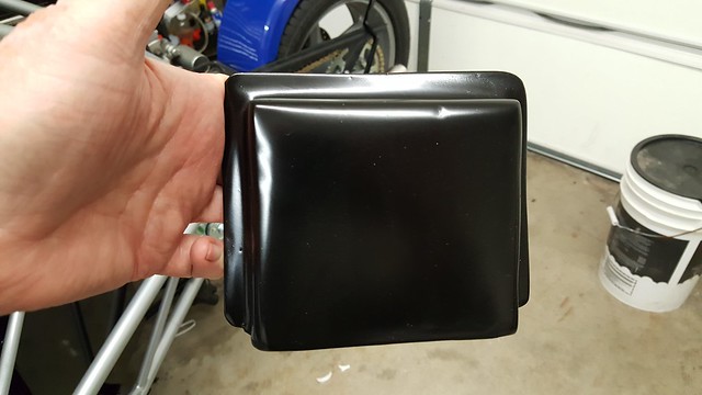 I molded an epoxy and fiberglass material cover for my engine control module. The module snaps into place and will be mounted on the engine bulkhead.  This is where the module will be mounted. Pedal ends of the throttle and clutch cables 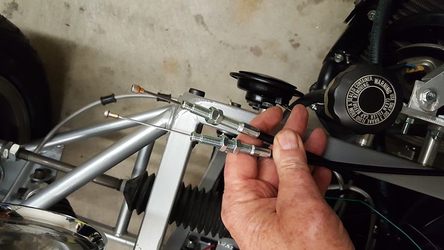 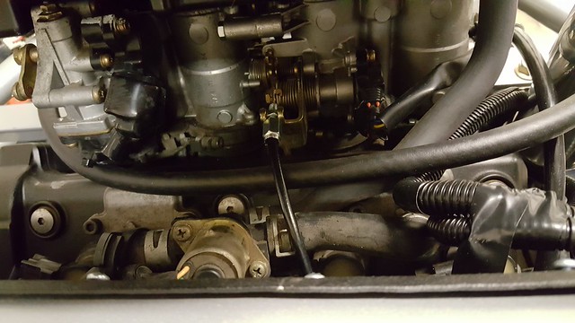 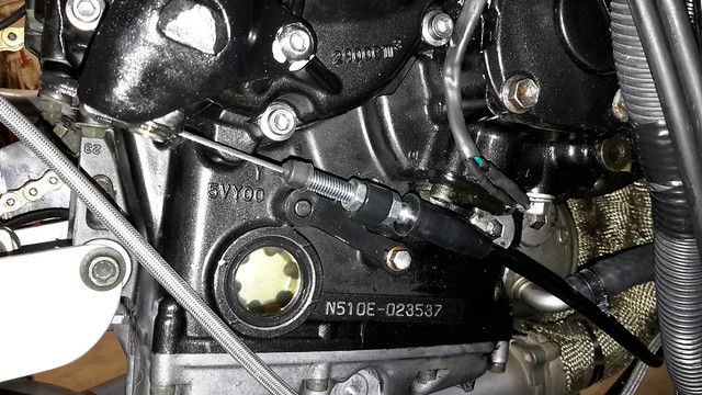 Clutch cable from Motion Pro |
|
|
|
Post by roger on Mar 4, 2019 1:07:54 GMT -5
I managed to get some work done today. I installed the right side tank and covered the electrics from the rear in wire loom. I also connected the cables for the throttle and clutch to the engine. I completed the mold work for the engine control module cover. I need to file the flanges so the are flat and squared off. The ECM simply snaps into place and is held there by the cover. I also connected the fuel injection hoses.. (yes they are for fuel injection) My next project is to install the surge tank and connect the electrics and all hoses. I also want to see if I can design a cover between the rear of the air filter to where the rear shock connects to the upper mount. it is a good place to fill in. 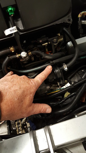 This is the area that I want to fill in. It will be a good place to stash the tip over switch and the atmospheric sensor. I am pointing at the supply and return fuel lines. Below is a longer shot of the same space. 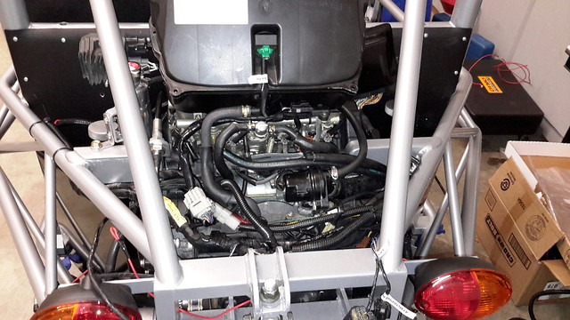 I have read the comments carefully. I see there are two schools of thought on the use of an ASB system and Lineal springs or going to progressive winding. The current springs I have installed are lineal and are the standard shock and spring set offered. The preload has been set to about mid range and I will evaluate which way to go when that part of my build comes around. I also have brake fluid rated filler hoses from my reservoir to the master cylinders. The Massachusetts inspection system does not require them to be in plain sight, but it is a good idea. Mine can be seen with a little effort without removing the bonnet. I appreciate the information on the overheating issues experienced by other TR1KE builders. I have two cooling fans installed on the radiator and made sure to insulate wrap my exhaust headers with titanium wrap. My engine is a 2005 and is equipped with an oil cooler. I am not sure if the older models have this system or not. I also installed an auxiliary tank designed to eliminate air pockets and keep the antifreeze flowing. I have seen these tanks on almost every TR1KE on the forum. Temperatures here can soar up to 39°c (100°f) if overheating is an issue, I will need a larger thicker radiator.... $$$$ I have the experience of building my Eco-Exo-R and routing the brake lines were somewhat tricky. I ordered the same brake lines for the TR1ke. They are flexible stainless steel wrapped lines from HEL. I have a little slack in the lines to compensate for compression and tension. I have yet to secure the lines to the suspension, but that is approaching quite rapidly. Thanks for the great discussion.... Roger Worcester, Massachusetts Like Stuart said above, any over the counter sway bar can be heated with a Mapp gas torch till it is cherry red and then bent to shape. We have done this many times and have not weakened the bar. If you support the bar as far out as possible it will work. It does not really act as a spring in most sense, when the left wheel is pushed up, the bar rotates in its bushing and will pull the right wheel up somewhat to keep the platform level. To act as a spring you would need to solidly mount it at the frame on both sides, but when mounted in rubber or a Poly bush it will rotate. True it will negate the Independent Front Suspension slightly. I do like progressive wound springs. Just a challenge to get the two rates right. With a total vehicle weight of around 750 pounds, linear style springs could possibly be dialed up enough on the preload to counter chassis roll. The cost would be measured in ride quality. I don't want a "go cart" but something I can ride long distances. Installing an anti-roll bar would not be impossible to do, just as installing a progressive spring such as Erik has would be quite easy. Before I do anything, I am going to do some serious testing. I have access to a rather large paved parking lot. It is in an industrial area and I could do some controlled turns without worrying about running off the road. I have to admit, I like the idea of progressive springs if I cannot achieve a good result by stiffening up what I have already. I will look through Eriks threads to see if he posted the spec's on his progressive spring set. I would also enjoy hearing from other builders that have installed an anti-roll bar or have experimented with an ARB. I am curious how it was installed, what worked, what didn't. Thanks DaveJ for your input..... Roger Worcester, Massachusetts I have been thinking about the overheating issues on the TR1KE that other builders have experienced. I am curious about the nature of the overheating and what was done to fix the problem. As I mentioned in earlier posts, I have a 2005 donor. The radiator is curved and came with dual cooling fans. I also installed a "carbing" tank to eliminate air in the system and to insure the water level in the engine is always maintained. There isn't exactly a free flow of air around the engine as it is installed on the TR1ke, but it isn't enclosed either. If any builder experienced overheating whether on the road, or in traffic queue what did you do to fix the problem. A larger capacity custom made radiator would be very expensive. If anyone wants to add their comment on this topic I would appreciate the input. Thanks Roger Worcester, Massachusetts  View from the front 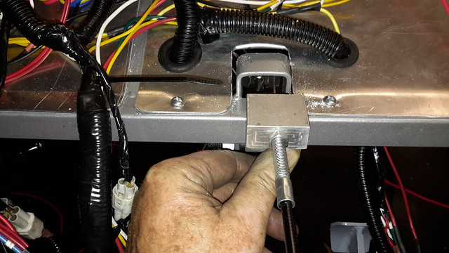 It is time I had the accelerator connected. I had a piece of 1-1/4" square stock aluminum. I milled out, drilled out! Tapped out and in general made the under bonnet accelerator cable mount. I also had to fabricate the pedal. The one that came with the kit was cut off to short and the cable scrapped the cross member. I figured if I had to modify the pedal, I may as well make a new one that fits my foot angle and comfort zone. I need to get a return spring mount and I will be finished that project. Roger Worcester, Massachusetts |
|
|
|
Post by roger on Mar 4, 2019 1:18:55 GMT -5
PAGE 5 I've seen some used an additional fan switch to turn the fans. I do not recall anyone installed a bigger rad so I guess it's sound. However, do imprint engine oil cools down way slower as cooling water. turning on the fans manually is not going to prevent oil temp reduction soon. When the oil gets too hot it could break the engine which R1 track bikes experienced. The expansion bottle is just a tool to remove trapped air in a cooling system routing where the original cooling sytem has not been designed for. When this is set up properly it is not going to help you cooling down the water it's surface is too small to dissipate heat. Erik I have done about all I can do to insure the cooling system works. The fans, the radiator lines, and auxiliary tank are all installed and should keep the engine within a normal temperature range. With the radiator lower than the engine, the Auxiliary tank is necessary to keep air bubbles out of the system and to "burp" the system in an initial fill. A cooler engine equals cooler oil. Anyway, this TR1KE will not be a track car. Running any engine at its upper limit can cause a long list of problems, among them them are overheating issues, oil breakdown, metal stress. I figure if I drive like I always do, the engine will operate as it was designed without any issues. However, I like the idea of a cooling fan override switch. It might be worth installing. Thanks for the input Erik Roger Worcester, Massachusetts If I have over heat issues, the way to go for me will be to probably add a 3 or 4 pass radiator. The single pass in the stock Yamaha R1 may be good for OEM purposes. When you add 300 pounds of extra weight and a driver and passenger then the dynamics have changed and the cooling system has not. The installation of a REAR mounted radiator might be what the doctor ordered. Not only a rear radiator, but a larger capacity all polished aluminum and custom made aluminum shroud and cooling fan..... all on the rear.... (maybe) The multicore radiator probably will be a great approach if you have heating issues.  I had to make a small modification to my clutch pedal. I had to put the dogleg in the cable end of the pedal. This compensates for extra length I had in my cable. It works great and all I need is to install the bolt for the stop. 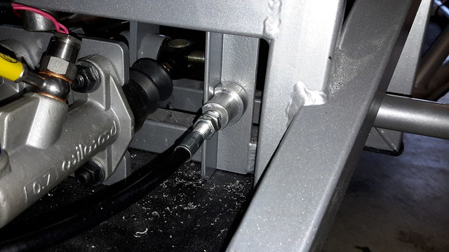 I had to make the clutch cable (pedal end) shoe, or mount (what ever you choose to call it) I had a little round stock aluminum and just cut it down on a lathe then milled one side of it flat so it would not rotate every time I pushed the pedal. The cable end was drilled and threaded 8mmx1.25 pitch. The end that faces the pedal was drilled through then cut down to 7/16" and threaded. I installed a nut and washer to hold it in place. I have to wait for the paint to dry on the pedal then I will install it tomorrow. All is good so far. Roger Worcester, Massachusetts If anyone has experienced fuel tank leaks or broken tabs, please contact me... Thanks Roger Worcester, Massachusetts Tall tanks are susceptible to high loads on the base mounts and I would recommend that 2 straps be fitted that clamp the tank to the rear bulkhead from the floor, L shape if you will. I read somewhere (can't remember where) that a builder had used double sided tape to stick a tank to the bulkhead BUT a drip of petrol would soon relieve it of its stickyness. |
|
|
|
Post by roger on Mar 4, 2019 1:33:56 GMT -5
Since I have a considerable investment in my fuel tanks, mods and powder coating, I am reluctant to go through another modification that would again require additional rework. The true answer is to beef up the mounts at the bottom of each tank and add a means to secure it from the top such as a threaded stud for an "L" bracket. This should be done from the source manufacturer along with doing away with the open vent and adding a rollover vent check valve as well as adding a barbed fitting to secure fuel lines to the tank. Roger Worcester, Massachusetts Here is where I am an the fuel tanks. I have given this a little thought and am STILL examining my options. The most economical thing to do is leave things as they are and strengthen the mount tabs and proceed as normal. This would be okay but it requires the tanks to be connected running lines near the exhaust manifold. This disturbs my chi a bit. The next step is to remove the two (2 gallon) fuel tanks in the engine bay and then install a fuel tank behind the drivers position on the left. I already have a 3.9 US gallon surge tank with OEM fuel pump behind the passenger seat on the right. The additional tank the exact same size would yield a total of (about) 7.8 US gallons. What this does is open the engine area up for air movement to aid in cooling. It also moves the C/G forward a bit and if there is a fuel leak from filling or loose connection it reduces the likelihood of a fuel related fire. A fabricated tank would cost about $350.00, powder coating another $60.00. Other mounting options would be to add a tank forward of the passengers footrest. I have not considered this yet. It would add a lot of additional weight up front, but there is space to install it there. Okay... If I go with a new tank behind the drivers seat, I am looking into relocating the radiator in the right rear location and adding a functional air scoop.... the radiator I am looking at is an aftermarket aluminum racing model. It is made for the 2000 and 2001 YZF R1 yamaha. Since it is aluminum, it would polish up and look nice and could be mounted high enough to do away with the burp tank. So far, these are just brain storm ideas. If you have any suggestions to add, please feel free to add them. I am very interested in any information regarding rear mounted radiators on the TR1ke. Roger Worcester, Massachusetts Moving the tanks to the correct side of the "fire wall" is a great place to start. Securing them by bolting down, (not up as per the build guide) is also a great move. Top mount or strap, essential. COM shift is in the right direction. Please see Rocket "Important builder guidance notes", sticky at the top. It is suggested that a fuel pump inertia switch is fitted. A filler cap with a key attached to the ignition key is also a good idea. A requirement for IVA but not for the MSVA trike test. No idea why, we can all drive off chucking fuel behind us. Do remember though that if you bolt the tank to the floor then what if it leaks. Fuel around your feet? Maybe a bund is required and a cover as per IVA, this is a vehicle after all not a motorcycle. Radiator upfront in direct air flow has to be the best place, the pipes feeding it add to the water volume and are therefore potentially cooling assistance. It's a significant additional volume which could not dissipate heat as well when isolated and could hold temp range at a higher range for a longer time. Hiding the pipes in a center tunnel does not add extra cooling because the air in the tunnel acts like isolation buffer if without turbulence. The material of the pipes (alum tubing vs rubber hose) is a factor too. pipes in the open air may cause severe skin tissue damage if not addressed properly which needs proper care. good luck! Sorry to have to disagree Erik. I do appreciate your opinions and help offered but we must observe scientific facts. Heat will be dissipated from the uninstalled pipes in the tunnel. The heat within the pipes will heat the cooler air around the outside of the pipes until it reaches the same temp, the air will then dissipate heat through the tunnel wall in search of cooler air. However air is not a good conductor of heat so to improve heat loss in the pipes we could consider the convection principle. Cutting holes in the floor of the tunnel and fitting a long vent grille to the top should help cooling. Heat rises. Let me see. If the engine has an OEM radiator and cooling fan(s) and the engine is running at an idle, it should not overheat. The fans will induce cooling air flow should the thermal switches call for the fans to come on. When the engine is under a load and moving through the air, it again should not overheat (if everything is working as designed) The actual location of the radiator is not as important as the cooling dynamic surrounding the placement of it. As long as the radiator is placed where air flow is unobstructed the engine should not overheat. Introduce a larger capacity radiator and the cooling efficiency improves. The extra cooling capacity outlined above by the aluminum cooling tubes dissipating latent heat is valid. If you move fluid from the heat source it will cool traveling through the piping. You can do "heat loss calculations" on this but the best way is to realize the amount of heat loss isn't sufficient enough to calculate or count as a solid cooling factor to keep the engine within limits. If cooling fins were added, then you could say, "YES" it would a cooling factor much as the heater coil in your car would help cool the engine. So, the bottom line to this as I see it is to keep the radiator up front as in traditional design manufacturing. However, if there were enough induced air through an oversized radiator (thicker/more coil passes) it would be as effective placed close to engine as I outlined in a previous post. The Eco-Exo works great with the radiator place behind the bulkhead. The only way to find out is try and succeed or fail miserably. Heck, even Thomas Edison knew 1200 ways not to make a light bulb. I figure I could find out how not to cool an engine at least once... :-) Roger Worcester, Massachusetts Sorry to have to disagree Erik. I do appreciate your opinions and help offered but we must observe scientific facts. Heat will be dissipated from the uninstalled pipes in the tunnel. The heat within the pipes will heat the cooler air around the outside of the pipes until it reaches the same temp, the air will then dissipate heat through the tunnel wall in search of cooler air. However air is not a good conductor of heat so to improve heat loss in the pipes we could consider the convection principle. Cutting holes in the floor of the tunnel and fitting a long vent grille to the top should help cooling. Heat rises. You must have misread my post: It's a significant additional volume which could not dissipate heat as well when isolated and could hold temp range at a higher range for a longer time. Yes the pipes will heat the air, the air will heat the tunnel and the tunnel will dissipate the heat to the outside air. As I mentioned this will take longer to reduce heat out of the cooling system which has an significant increased volume as a negative side effect as well. The good thing is it should take a bit longer to overheat. Cutting holes and a vent grill may not be desired it could make the loom very sensitive for dirt and water and may cause copper corrosion. |
|
|
|
Post by roger on Mar 4, 2019 1:52:28 GMT -5
PAGE 6 Not trying to argue here, just my opinion based on what I have found in some past racecar builds. If you take a 3/4 inch (19mm) copper pipe 10 foot long, then twice for going forward and back, you have added over 1/2 gallon of fluid volume. This copper pipe will dissipate a lot of heat to the free air if allowed. Routing it thru the cockpit and insulating it so that heat does not affect the riders will lower that heat loss some so routing it to the outside somehow is needed. We found that using an infrared probe clamp that we lost about 20 degrees F between the engine in the rear and the radiators inlet then another 8 degrees from the radiators outlet and the engine on the return. Biggest loss was in the radiator and the lower over all temp dropped from 215F down to 150F. The 195 degree F thermostat was closing, opening, closing... SURGE. Roger is adding a surge tank and this was what we had to do also. Where I would spend most of my cooling mods would be in OIL cooling. Replace the small factory cooler with a remote mounted larger unit, with a temperature by-pass adapter so oil will reroute back to the engine only when cold. That oil cooler should have a relay switched on fan to pull air thru it when at slow forward speeds or when stopped in traffic. That car we built was a salvaged 1968 Porsche 911 that we put a large front wheel drive V8 in the back. So cooling was a big engineering issue going from a air cooled 2L H6 to a water cooled 7L (425 ci) V8. That mid-engine mounted V8 took up all the back seat and cargo area. This was when a crashed 911 was worth about $30 in scrap.  The actual extra volume would be 188 ounces calculating 20 feet of extra length using 1 inch tubing. There are 231 cubic inches in a gallon of water. This means about 3/4 of a gallon of extra coolant. There is a difference cooling a mass of liquid contained in a vessel vs cooling the same volume through a pipe. The OEM radiator and oil cooler should take care of the this engines requirements. I will keep this entry bookmarked for future reference. Thanks Dave Roger Worcester, Massachusetts I will throw this out there. Has anyone had any luck using a bender on aluminum tubing. The bender I have in mine is sometimes called a Hickey Bender, used to bend EMT commonly called conduit. I didn't know if the tubing would kink or crush if I tried to bend it. I want to do away with some of the radiator line splices and hoses by custom bending the aluminum to meet with the radiator and engine inlets and outlets. The other question that was pitched by a friend was to look into using soldered copper lines instead of aluminum and adding the fittings and elbows as necessary. I am not sure copper is the answer, but just do not know why. I would be afraid the soldered joints would work loose or split. Anybody have any thoughts on this. Roger Worcester, Massachusetts On copper tubing, using a high tin/low lead alloy solder is good to about 230 Degrees at 15 PSI. But if you step to a brass based BRAISING rod it is good for about 500 Degrees @ 200 PSI. Silicone lined brackets should isolate it from movement. But these are ratings at about the 100% factor for use in low pressure STEAM boiler plants, so 215 Deg F and 18 PSI should be OK outside the cockpit safely. Its been over 25 years since I dealt with steam heat systems. On bending the aluminum, look up annealing process for aluminum. I would anneal it, pack damp sand in it, bend it and then clean the sand out. It will age harden in a day or so. Surge tank in place on the right side of the TR1ke 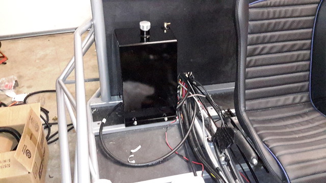 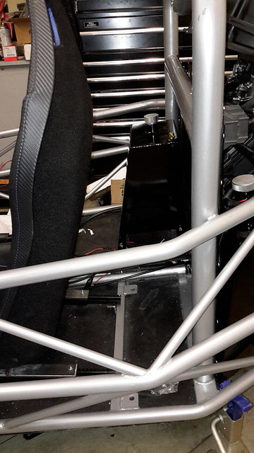 I finally got off the fence and called Dove Racing LLC. The surge tank that came as an option when I originally bought the kit contains the OEM fuel pump. It mounts on the right side behind the seat. I spoke to Peter Dove and gave him the measurements needed to have another tank made. Once I remove the two saddle tanks in the engine bay and install the new tank behind the left seat my fuel capacity will be 7.8 US gallons. Currently it is 8.1 US gallons, a loss of 3/10 of a gallon or about 30 US ounces. The overall design of the TR1ke provides enough leg space for me, the seat and fuel tank. I am 6 feet tall so I am not short nor am I Andre the Giant either. Once installed I will have enough fuel to drive about 200 miles if I get 30 MPG. I am hopeful for better mileage, but we will see. I hate it that I had my fuel tanks powder coated, and modified to accept an in tank roll over vent safety. It represents a bit of money spent that I am not going to put to use on this project. However, the safety factor in getting the fuel tanks out of the engine bay and in front of the bulkhead is a solid move and is worth the cost of keeping me from becoming a statistic. Everyone should read the sticky note warning concerning the fuel tanks and the front suspension. Roger Worcester, Massachusetts 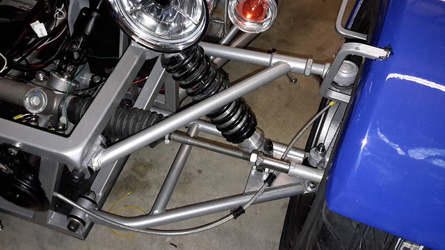 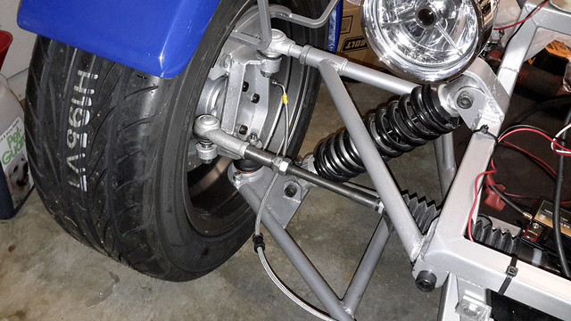 I am asking about the NEW vs OLD suspension A arms. This is what I have. How do I tell if it is the old suspension or the new and improved? If anybody can tell me, it would be great to know. Roger Worcester, Massachusetts It is possible to get a 90 deg bend with a simple compression bender. It does start to flatten the tube as you can see but I the section surface area is the same so no restriction offered. A fixed radius bender with a follower would be better. I have a spec sheet for the tube if you need it. Stuart The lower bones on the prototype were Rocket but upside down, track width was not wide enough. I suggested RTR look at widening and I think they added 40mm. No idea why yours have bends in the tubes, I notice that some have bends in the top bone too. You can tell if you have wider ones if you look at the position of the lower shock mount, if this is at the edge of the ball joint plate (as yours is) then I suspect it is the longer bone. It would be interesting to hear what you track width is. I notice you have the fabricated uprights with Focus stub axles. Adding the stub axle to the plate upright makes them very heavy but they increase track width beyond the Ford Cortina geometry, as used in the alloy rally design alternative. |
|
|
|
Post by roger on Mar 4, 2019 2:00:03 GMT -5
I have been holding this back, but about a month ago, I was installing the dual exhaust "Y" pipe and while lifting the swing arm with rear shock disconnected, a coil became lodged in swing arm and broke a sizable chunk of the swing arm. I found a NICE replacement on ebay and after removing the bearings and cleaning it up, I delivered it to my (not so local) powder coating company. I opted to do a little something different and have it coated with a "chrome luster". When I bought the replacement swing arm, it came complete with an aftermarket aluminum R1 chain guard with the R1 logo cut out. It is also getting the chrome luster treatment. In addition to those items my front turn signal mounts and the rear fender anchor are all getting the same sort of process. The photo shows the damage. It also shows the extra heavy duty real coil spring responsible for the damage. It probably would not affect performance, but it simply looks bad. All things considered it was a minor setback and I have ordered new bearings and caps. The center tube is okay.  Stuart: My track width measured between the mounting flanges of the hubs with rotors installed is 66.5 inches. Measured at the outer edge of the tires it is 70 inches. Center tread to center tread is 63.5 inches. I have 15X7 Konig wheels with a 38mm offset. As an added piece of information, I have yet to do a front end alignment except to get the tires close. Measurements above were taken as close to the center of the hub as possible. Roger Worcester, Massachusetts excellent, thanks, my original calcs and C.O.M guesstimates were based on 1600 mm track width and 2600 mm wheel base, yours is close to that. It is quite possible that the alloy upright option is narrower than the Ford Focus rear stub axle bolted to the fabricated uprights. I never has the opportunity to measure or weigh a finished tR1ke. It would be interesting to know the corner weights and approximate COG with an assumed drive and passenger on board of say 80kg each. I would like to think the COM would be half way down the wheel base and no more than 500 mm above ground. Maybe I will never know. One wheel at a time on bathroom scales would provide some of the missing info. 380kg empty? I just had a conversation with Peter Dove of Dove Racing LLC. He is the designer of my 3.9 US gallon fuel surge tank. He has the design plans for several other tanks that incorporate the internal OEM Yamaha R1 fuel pump. I asked him if he could have a tank made to fit behind the left seat without a fuel pump. He is currently having that done. He has not been available for the last week or so, but has returned home and will be able to design and build the tank for me. I did not seek any fabrication work here locally. Not to many companies do this sort of work on an individual basis. They will want to make 10 to 20 and not just one. I have to mention that the custom tank is not available except through Dove Racing LLC. It is not an Exo Sports Cars product. This is simply one of many custom made accessories that DRL provides. Roger Worcester, Massachusetts Roger ... lookin real good . Did you tell me that the Tr1ke is finished? If so , will you be posting pictures of the finished item or how about some pics of where you are in the build ... the entire vehicle ? Very cool. |
|
|
|
Post by roger on Mar 5, 2019 1:31:09 GMT -5
PAGE 7 Fred: It is nearly complete. I am waiting for the fuel tank to be manufactured and sent. I have all the difficult stuff done, wiring, cooling and exhaust. The few other items will be done as I have time to get to them. I need to take care of some things that carry a higher priority, so work on the project has been slower. Once things get back on track I will be at it again. (STAY TUNED FOR FURTHER DEVELOPMENTS) Roger Worcester, Massachusetts 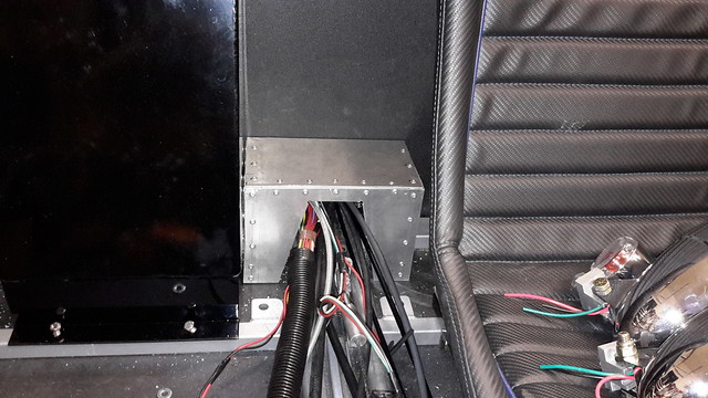 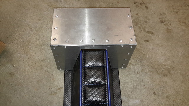 I am making a plenum box at the end of the tunnel. I will shorten the tunnel by 4.5". The plenum is 6" tall and 9" wide and 5" long. I will CAREFULLY cut a larger opening in the bulkhead and affix the plenum. This allows the hoses, cables and wiring some strain relief. It also keeps things clear of the exhaust headers. Not shown in the above pictures is the opening I cut in the bulkhead for the fuel and tank vent lines. I will take a couple of pictures of it once the tank is permanently placed and the fuel lines are properly routed. That's it for now. Roger Worcester, Massachusetts I finally got my swing arm and other parts back from powder coating. They were the most beautiful gloss black anyone has ever seen. You could see into the luster a foot deep. I was impressed with the quality, amazed at the quick turn around, dazzled by the low price, and since I ordered Bengal Silver, you can only imagine my disappointment. They did a quick media blast and recoated. I got a call about 4 hours later saying the pieces had been completed in Bengal silver... and they were done with the same care and quality as the black coating. The swing arm got new bearings and seals, before installation. I also bought a $10.00 chain master link and the quite pricey rivet tool and installed the chain as well as the rest of the swing arm components. Tomorrow the TR1ke will be off the jack stands and back on the floor. It's been a good day to work on the build. I will post photos tomorrow. Roger Worcester, Massachusetts 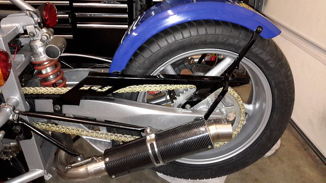 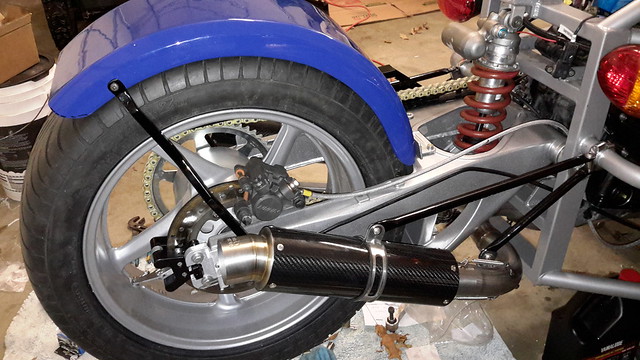 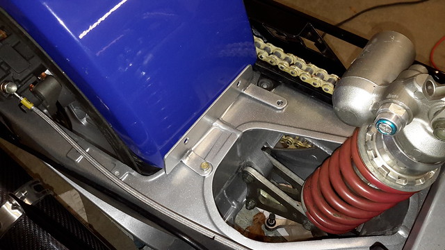 The new swing arm went in without any problem. The powder coating was quite nice and the price was fair. The eBay swing arm was not scraped or road rashed. I received it complete with the R1 chain guard, axle and spacers along with brake mount and the hard rubber cover to prevent the chain from damaging the swing arm. If you look hard enough you will see I still need to connect my parking brake cable and secure the cable and lines. The rear fender mount shown in the 3rd picture may need to be replaced and remade with heavier material. It acts as an anchor and has no real stress applied to it. I will give it a go and if it starts to fail, crack or prove inadequate I will give it the boot. The finishing steps in getting the swing arm area completed is to wrap the exhaust "Y" pipe, trim the trailing edge of the fender and shape it. The parking brake cable to caliper link also needs to be powder coated... (next batch) Roger Worcester, Massachusetts It has been a little manic here. Nothing to do with the build but just the "other things" that complicate life. Hopefully things will settle down soon and I can resume life as I knew it.. :-) . I got a progress report on the new tank that goes behind the left seat. I should have it in a couple of weeks. The body of the tank is exactly like the one that came with the kit. The new one will not be floor mounted, but attached to the bulkhead. Both tanks will be the same height. I am modifying the mount on the tank that came with the kit. I will place spacers beneath the forward mount to lean it back against the bulkhead. I will attach a restraint at the top of the tank and anchor it to the bulkhead. What that will do is align the two tanks so they look like a matched set. They will be tucked behind the seats and the method of mounting will not be obviously visible. By the way the bulkhead will be reinforced to support about 30 pounds of fuel and tank. Supports will be 3/16 X 1-1/4" flat stock... (Maybe aluminum, maybe steel) More pictures will be posted once I have the tank. In the mean time I will be working on some more of the details. That's it for now Roger Worcester, Massachusetts I have not posted in a couple of weeks. I needed to temporarily suspend my time on the build and place it addressing family matters. Everything looks promising and I will probably be back on my build in another week or so. I received a phone call from Peter Dove of Dove Racing. He informs me my fuel tank is nearly ready to ship. It is completed, with the exception of the filler neck, which I sent him, last week. As it stands, the weather has been Spring like but that was only a brief tease. This morning brought a dusting of snow and below freezing temperatures. I will post more photos and information on my progress as I work on it. I want to have it ready for inspection, and on the road before the end of May. Roger Worcester, Massachusetts |
|
|
|
Post by roger on Mar 5, 2019 1:39:07 GMT -5
I received the custom fuel tank yesterday from Dove Racing to replace the two engine bay mounted side tanks. I immediately drilled the mount holes and took it to Central Mass Powder Coating. In the meantime, I will be buying the pieces to mount on the backside of the aluminum bulkhead to "stiffen" it to prevent flexing and getting stress cracks. The tank itself is very sturdy and made of heavy gauge aluminum. Definitely not the same material used in the OEM tanks. I was able to match the design of the fuel caps and filler necks as well as the placement of cross feed lines and vents with the surge tank that I ordered with the TR1ke. They are nearly a matched pair. I will post photos as I do the installation. It should be back from coating by Wednesday. More later.... Roger Worcester, Massachusetts Due to the Blizzzzzzzard... the powder coating company closed for 2 days. My tank should be ready by close of business today, and available for pick up tomorrow morning. I need to be sure to pick it up because Saturday we are getting more snow on top of the 13 inches we got Tuesday. I removed the drivers seat and cleaned up the wiring, cables and lines running through the tunnel. My next step is to mount the inertia switch that cuts off the fuel pump. It will be mounted within arms reach of the driver. After the tank is installed, fueled and engine running properly I should be well on the way to the big inspection. With all that, no photos to post just yet. I want to have both tanks in place then do the pictures. More to come later.. Roger Worcester, Massachusetts 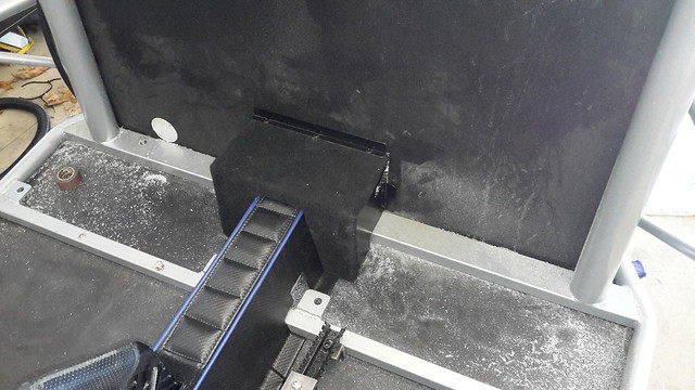 The plenum box and tunnel. The plenum will be secured with common hardware. The inertia switch will be housed in the box as well. 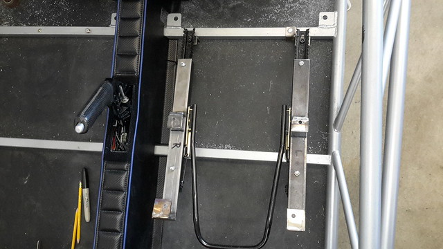 The seat mounting rails. Now to copy it and install it on the passenger side. (That on the right side here) 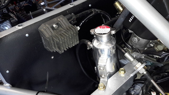 Burp tank all connected along with that HUGE rectifier. 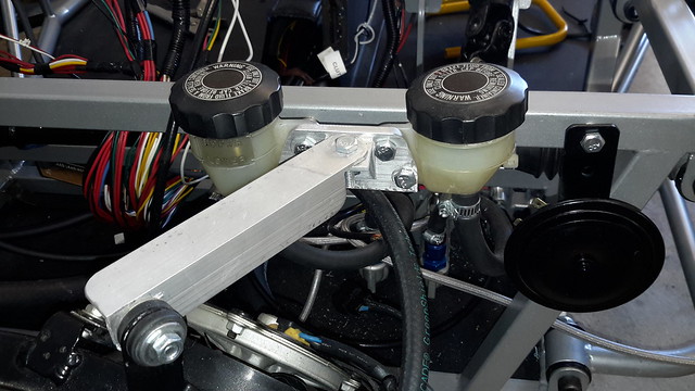 My brake reservoir mount. Also the left radiator brace connects to cluster as well. I just finished fabricating the passenger seat mounts. I need to let the pieces dry for a day or two. I also made the mounting system for the new fuel tank. Again, it needs to dry. All of the mounts, for the seats, the fuel tanks and tunnel plenum need to come together at one time. All of them need to be completed and assembled as a unit. My next stage is to make the heat shield for the exhaust headers. As I mentioned previously, all of the wiring, cables and piping pass very close to the exhaust and I would feel better with a positive barrier between the hot things and the cold things. The next set of pictures I post will be a sequence of pictures with each stage of assembly for the twin fuel tanks, the seats and the tunnel. Should be ready in a few days. See you then Roger Worcester, Massachusetts 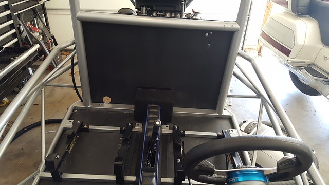 The seat sliders are all installed and coated. Next comes the fuel tanks. 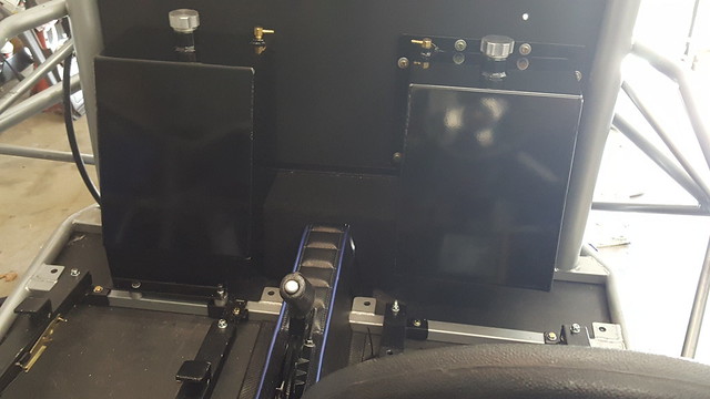 Each fuel tank is about 4 gallons. The fuel will always be balanced because of the equalization lines between the tanks. 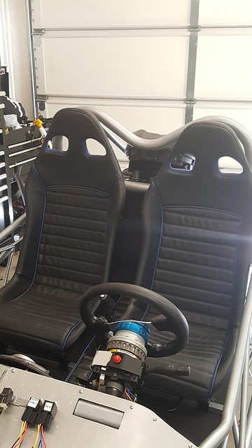 The seats are a perfect balance. Both are the same height and there is plenty of room between them. (It's getting there)  The angle of the seat matches the angle of the tank pretty closely. |
|
|
|
Post by roger on Mar 5, 2019 1:50:34 GMT -5
PAGE 8 Good for you Roger! Everything looks top notch but that was expected. I just do not know if you can handle that much power at your age. Ha Ha:) Thanks Eddie...I just need to get the hoses connected between the fuel pump and the fuel rail and add gas and it should be ready to start up. I ordered a pair of blue "Cipher-Auto" cam lock safety harnesses. They will come complete with mounting hardware. I tried to find out where the belts were manufactured but no luck. CARiD sells them. Currently I am designing a small heat shield to place between the exhaust manifold and the hoses, wires and cables that pass close to the heat. I already have the manifold covered with DEI titanium wrap. The heat shield will be a little extra insurance. I have yet to fill the cooling and brake systems. I have found it necessary to open lines to re-route wiring, cables and the like. No sense in making more work by draining the systems, or purging air from the brakes again and again..... I am at a point where I need to buy some top quality fasteners to permanently secure and bundle all that "stuff" that makes the TR1KE run and stop. I will be posting more pictures later in the week. Videos are now a bit of a problem to do. Photo bucket is a PITA to load videos to and YouTube is slow but not as bad. I suppose I could do a walk around video once the snow has melted and I have the TR1KE off the jackstands. With that, I will have another cup of coffee and wait for the sun to come up. My best to everyone.. Roger Worcester, Massachusetts Just a quickie... I got all my fuel hoses and tanks fully connected. Friday a friend will come over to help bleed brakes and burp the antifreeze. With the fuel tanks in solid, it should start, run and idle down. I will be able to test the gauges, cooling fans and the rest of the stuff that needs verification on Friday. I will do this outside. This will naturally depend heavily upon having good weather. I do not want to run the risk of a fire in my attached garage with its maiden startup. Got to go to an appointment, so till later.. Roger Worcester, Massachusetts Yesterday wasn't the banner day I thought and hoped it would be for the initial start up. In the first place it was cold enough to freeze fire and then came the snow squall. More than a dusting but not a blizzard either. As a result I decided to simply open the garage door and do the start up inside. I added about a quart more or less of gas. I then noticed it was pouring out as quickly as I was adding it. I quickly booted the trike out the door, and placed a drip pan beneath it. I spent several hours cleaning up. Yes, soap and hot water getting the fuel out of the floor pan and from what leaked onto the garage floor. I froze my nubs off. What I found was a faulty o-ring inside the fuel pump on the return line. It had hardened and became brittle. The fuel shot past it quite easily. I was able to remove the nipple and installed a new o ring. It is now fuel tight. No leaks or drips (so far). (Just a quick insert) at no time did I have the battery connected during this portion of the test. Since the weather was rapidly going from bad to worse, I decided to postpone the official start up. What I did was to simply put enough fuel in the tank to test my repair. I connected the battery and switched the key on and pressed the starter button, it started right up and idled. I only let it run a few seconds. There was no coolant in the system. All and all the procedure could have gone better. I could have done without the leaky fuel part, but as it stands, the engine runs and the system wiring has been proven. Not quite textbook, but didn't burn the house down either. Lucky for me the "Misses" was out with her friends. Today will be spent getting a few spares like antifreeze, wire ties and adel clamps. I will also install a few bits and pieces on my motorcycle. Even with the nasty weather, it is still Spring and riding season is when you can get it. It is supposed to rain for the next few days. Perhaps I should have built an ark, but what would I do with all those animals. Cheers everyone Roger Worcester, Massachusetts  The good old days when men were men and cars were..... well long, low and unique. I am not sure what it is, one thing for sure there is a lot of hand work and skill in this. Yesterday wasn't the banner day I thought and hoped it would be for the initial start up. <<<SNIP>>> Even with the nasty weather, it is still Spring and riding season is when you can get it. It is supposed to rain for the next few days. Perhaps I should have built an ark, but what would I do with all those animals?
Cheers everyone Roger Worcester, Massachusetts |
|
|
|
Post by roger on Mar 5, 2019 2:02:23 GMT -5
I tried Imgsafe.org. It works well with pictures, but it seems as they do not support videos. The pictures load quickly and accept most formats. As far as doing g a BBQ shop with Fred, well, he is the guy that you'd want to be in that business with. Of course you could have the first "Chunk O' Skunk. If you like.... Roger Worcester, Massachusetts Okay, if I did everything correctly, I loaded this link to Youtube. MY INITIAL START UP.   I used this aluminum backed heat barrier. It has an adhesive back and sandwiches a layer of fiberglass wrap beneath the aluminum. I wrapped each tube individually, then applied a second layer over the top to bind the tube and add additional insulation. This stuff is good for 500° F direct contact. I also added additional wrapping over pressure points. Next is to add antifreeze. It does start, run and idle. More later Roger Worcester, Massachusetts Roger You are doing a great job! The insulation around the tunnel area will keep the tunnel cover nice and cool. Everything looks top notch and it looks like you will be on the road very soon. Excellent work on your part. Edward  Since you like the good old days here is something more your style:) Yep, that's a neat little trike. Wonder where it came from. It looks like it rolled straight out of 1930. |
|
|
|
Post by roger on Mar 5, 2019 2:16:38 GMT -5
PAGE 9 I got the TR1KE cooling system filled and purged. It was a bit of a bother with the purge part of it but nontheless,it is done. The cooling fans cycle on and off and it runs in the 180° to 200°F temp range.. mostly around 190°. The engine doesn't smoke, drip oil or coolant. I will be bleeding the brakes next then tweaking my clutch adjustment and installing the pedal stop. Just an quick note. I insulated the cooling pipes with an aluminized covered wrap. It has a high temperature fiberglass underlay and is self adhesive. At close to 200°F, the insulation was quite comfortable to touch. I put a photo in my earlier post when I was in the process of installing it. I still have the package it came in and will provide a picture of it just in case anyone might be interested. It is good for up to 500°F direct contact, so it is great for the cooling tubes. Roger Worcester, Massachusetts One of the miss-conceptions is a cold engine puts out more power. This is not true. A engine must operate between 180 to 210 Degrees F. If run lower that 180 deg's F the piston rings will fail much quicker. Anything over 210 Deg's F and the OIL starts to fail early and causes sludge. You are GOLDEN! And GOOD call on the cooling pipe insulation. Over on ReverseTrike.Proboards.com we had discussions on CLUTCH issues. A lot of builders using a high powered Motorcycle engine in a heaver than motorcycle trike, they were having clutch slipping issues at upper RPM. It was found that if you research clutch springs there are some much heaver ones than stock. But if you use a hand clutch lever it may be too hard to pull. But most builders have a foot fulcrum clutch peddle. I would also replace the clutch disc's and plates, JUST to have new and fresh surfaces. Just my opinions, YMMV. Hey Dave, hows it going? As I said in my previous post I had a difficult time burping the air from the cooling system. I got all the air out and now it operates like it should. The engine heats up very fast, the water pump is actually located in the oil pan. One end of the pump is the water pump and the other is the oil pump. It also has an adjacent oil cooler. The engine runs at a temperature higher than grandpa's old Chevy this is true. I already installed new clutch disks springs and plates. A word of caution when it comes to heavier springs. They put a lot of extra pressure on the clutch basket and if you get a little out of sequence tightening them in, you can crack the basket, or break it if you dump the clutch pedal. The perfect balance is being able to slip the clutch at initial take off and then prevent it from further slippage during a ride. The R1 engine was designed with hot rodding and doing wheelie's. It is made to do 120 MPH all day long and will Rev upwards to 13,500 RPM's. The engine will run hot and it will burn clutches out of it. You have to consider at 180 BHP, it is stitched together rather well. Clutches run less than $100.00. A drive belt in a Burgman 400 is at least that if not more. Clutches in an R1 are easier to change than the drive belt on a Burgman 400. I need to get a day or two of clear weather, no snow, and do the brake fluid installation, tighten down a few more nuts and bolts then do some test drives. Tonight we Get 3 to 6 inches on top of the 2 inches that fell today. We will have one of those "winter to Summer" seasonal changes with no Spring in the middle. I lived in the UK for 4 years. I remember taking full advantage of a warm summer day. They were rare and a treat. The norm was rain in the forecast followed by periods of precipitation..... or so it seemed. Roger Worcester, Massachusetts   This is the box the insulation I used for covering the cooling tubes. The small print in all of this is you need to make sure the surface to be covered (direct contact) is below 300°F. The adhesive is a limiting factor. Otherwise, it will protect up to several thousand degrees Fahrenheit of radiant heat. By the way, that box was about $100.00 USD and contained enough material to cover 2 cooling tubes 4 feet long and 1" in diameter. It also covered a span of 6" wide by 48 inches long. I had a (((((small))))) amount left over. Roger Worcester, Massachusetts I spoke to Peter Dove of Dove Racing LLC Trenton Texas. (Now there's a blatant plug) He is ordering me a set of Canards to place in front of the wheels. I gave the matter a lot of thought and decided I would install them and utilize or incorporate their mount with securing the bonnet. I am not sure what the lead time is but any time is alright with me. I understand the addition of the canards will aid in keeping the front tires on the pavement by providing about 25 pounds of downward pressure on each tire. My main reason is the simply look BAD-A$$!! As far as the remainder of the work to be done it is a short list. Secure the wiring,and coolant lines and do a little finish work and "Bob's your uncle" I'll be done. One of the items I will need to get help with is the alignment. I can do it myself, but it will go much easier with two. During this build I will not add an anti-roll bar before the state inspector combs over it. Once legally plated, and driven a few hundred miles, perhaps then... (maybe). There is always heavier progressive springs, but in the long run if I decide between the three options, the anti-roll bar is the way I will go if the handling calls for it.... and then it will greatly depend on how loudly it calls. As in previous posts mentioning the powerplant, the engine is 100%. No fault codes and runs in the normal heat range. This weekend will be a major push to get some things tightened up and cinched down. Until later... as always, pictures to come... Roger Worcester, Massachusetts Hey Roger you forgot a couple things. Better add to that order or you wont be able to change your shorts first time out   In my conversation with Dove Racing, I mentioned ordering a rear wing. After getting the price it was obvious it was going to drive my monthly budget past the comfort zone. I only ordered the canards. He told me he was contacting his supplier to get them the following day. As far as the wing goes, I will eventually get it, but not until a little later. The wing does look good placed over the rear wheel.. I can also see where the bags would be useful. I would have to see the trike in first person to see how everything flows... Bags, Canards and spoiler. Roger Hey Roger you forgot a couple things. Better add to that order or you wont be able to change your shorts first time out That looks great, the spoiler adds to the drama, the bags give a more balanced stance and the color scheme works well, details like seat belts matching the grp are always a good trick, oh and the air box, real nice. |
|
|
|
Post by roger on Mar 5, 2019 2:27:05 GMT -5
I will be giving a follow up call on the canards. Not sure when to expect them, but I did call Dove Racing LLC to get them sent directly to me. The wing looks wicked good. I thought I saw a C-6 Corvette with something similar. As far as Toto and the canards, Wings and bags. Well, I ain't in Kansas. A heads up Dave, I will be headed in your direction this June. I suspect around the 9th or so. On a long cross country ride. I will not be going solo this time, a good friend will be going with me on his Harley Tri-Glide.... Well thats it Roger Worcester, Massachusetts Hi, been thinking of similar wing in mini form for ExoR without welding but as a bolt on option. Any info on this possible? Many thanks Babr Babr: No doubt it would look cool, but since no one is manufacturing the Eco-Exo any more, the likelihood of getting a "one off" rear wing seems a bit of a reach without it costing the Earth. The wing part could easily be manufactured with a little help from a local fab shop. The real challenge is to make the support, and make it so it was adjustable, plus handle the constant downward pressure the wing would provide at higher speeds. It is all a bit tricky when artificial loading is placed on the suspension. Handling characteristics are changed because the CG is altered from a static position to a variable one depending on speed and angle of attack of the wing. A lot of the muscle cars built in the 60's and early 70's had rear wings attached to the trunk. These were mostly ornamental and probably had little or no effect on handling. The only exception was possibly the Daytona 500 and Superbird from Chrysler corp. Both were "B" body cars badged Dodge and Plymouth. If you come up with a working model, I'd like to see it. Roger Worcester, Massachusetts I have been sidetracked a bit from the maintenance and the build on my TR1ke. I've been preparing for a motorcycle ride to California and back. I will be leaving June 1st on a 1990 Honda GL1500 Goldwing. I've been busy getting it ready and doing the needed maintenance to get it safe and reliable. Once I get the brakes filled with fluid and their rear fender secured the TR1ke will be ready for a road test. I plan on doing this before I leave for California. It's true what they say it's all in the details. One of the details I have yet to finish is the addition of the front canards. I am still waiting for Dove Racing to acquire them for me. They are on order and should be here mid month. Once I get a road test done I will need to align the front end more precisely and secure the small bits and pieces that are left to be done. I will be adding the rear wing later this summer. I will add it after I have the road worthiness inspection completed. The less there is to inspect the more likely it will pass. Today I will place the scales under each tire to get the weights. Stuart asked me for them last month, but there have been compelling reasons why I have not done this yet. It is long overdue. My apologies Stuart. Roger Worcester, Massachusetts Today I will place the scales under each tire to get the weights. Stuart asked me for them last month, but there have been compelling reasons why I have not done this yet. It is long overdue. My apologies Stuart. Roger Worcester, Massachusetts No worries Roger, I assumed you had been busy with stuff. I still have my original calcs so will post them next week and add yours in. I was procuring my bathroom scale when my Mrs was at work. Not that she would mind me using it to weigh the trike. After I got the combined weight it was in excess of a thousand pounds after adding the sums. It just didn't seem right, but there it was. I asked my wife (once she arrived home) if the scales were accurate and she informed me that when the batteries get low for the LED readout, the accuracy tends to drift toward the high side. Soooo, I went to the corner market and bought 2 replacement batteries... (darned expensive little coin sized things) and installed them....correctly. It seems as though, the scales are just as inaccurate with new batteries installed. She headed out to do some errands and said she would pop by Wal-Mart and get a replacement. She bought a nice one It's made of glass. Not sure I want to test the compression strength of tempered glass. I am in the process of making a plywood pad to cover the glass. Let's see what happens Roger Worcester, Massachusetts |
|
|
|
Post by roger on Mar 5, 2019 2:38:04 GMT -5
PAGE 10 Roger, You may want to put the other two wheels on blocks as thick as the scale setup. It may make a difference or not. My thinking is if the two tires are lower then the lofted one will have a bit of "Jack" weight added. I am thinking of getting a replacement scale. The glass top on my new one looks a bit fragile to be placing a lot of weight on it. I am going out today and will stop by Wally's to see what they have. Ya just can't have to many scales Ya know! I might be able to do exactly what you suggested about the lofted weight, but doubt if it makes much difference. Well, time to leap into action. The day is started and I am not.... that's retired life.... Roger Worcester, Massachusetts 8669e1f034.jpg" Here is my math before I made the first mock up. I never got chance to finish it or weigh it and I think it got stretched etc. later, but it would be interesting to see how true figures replaced on the attached pan out. If your scales are not going to take it then a pair side by side sharing the loaded could work, adding the combined readings one wheel at a time. We don't need 100% accuracy at this stage of the game. Feel free to enter your numbers on the sketch. I got back from my motorcycle ride out west. It was about 10,000 miles or roughly 16,000 Kilometers. I will try to keep within the spirit of the forum and keep my comments focused on the build, but just wanted to say I returned all in good shape. My co-rider also managed a clean ride as well except for a small speed bump that caused a spot of bother, nothing serious. I will be posting some pictures in a few days. Upon my return home, I naturally was faced with a long list of tasks that needed to be taken care of, least if all was installing new hardwood flooring in two bedrooms, painting, and moving furniture and all that goes along with that. I found out my Prius was damaged and required some extensive suspension work, so decided to trade it in. Finally, the wife's car required a complete brake job.. in other words, a I have been busy since my return and find catching ones breath needs to be scheduled in.. I made a few notes as book markers for my TR1ke build before I left. I will be resuming my work on that. Basically securing the seats, the bonnet and rear fender. I also need to tidy the wiring and connect the exhaust damper module to the frame. That is pretty much it. Dove Racing has secured the canards for the front and the wing spoiler for the rear. I do not want to secure the bonnet until I receive that package. My headlights, and brake/tail lights are all wired and connected. I want to install a plug just inside the bonnet for the headlights and front directional lights so will see what I can locate at my local parts store today. That is the work remaining. When that is complete, I will Need to do the front alignment then make the inspection appointment and hopefully get my registration and title. I will be posting as I did before going on my motorcycle ride. Take care all. Roger Worcester, Massachusetts Well, I am going to see about flicker for the photo hosting. Not sure if it is free or not but I see Edward Van Belkom used it and his photos are still up. I am surprised Photobucket has done this, but imagine it was a sink or swim situation for them. As it is, photo hosting is currently a problem internet wide since photobucket is holding everyone's photos from being shown.... that is for their patrons that didn't dig into their wallets and ante up. I wouldn't object to strongly to a modest fee, but there isn't anything modest about the fees Photobucket is requesting their patrons to pay. I look at it this way, without the free account patrons, photobucket wouldn't have gotten this far, but now it seems we are simply flotsam and jetsam and have been tossed overboard for patrons with commercial interests and money. How does this relate to the TR1ke? It doesn't!!!! Also it doesn't to the Exocet, Eco-Exo or Replicar. We were all seeking to preserve our legacy by our posts and photos, but now we need rebuild years of detail oriented photos thanks to photobucket. Unless something changes, I can see every forum that used to use photobucket pretty much cease to function, or at least not at full capacity. Until something solid falls into my lap in the form of a free photo host, I cannot post photos, and that means no detail support. You know, " A picture is worth a thousand words" sort of thing. Okay, enough of that. I still and sifting through a backlog of small maintenance items to tidy up on my TR1ke. They are all minor in scope and once I get enough time to complete, I will be back with information on my progress. Currently it is the house that has been getting all of the attention, new floors, paint, closets and the like. Every time I pass the TR1ke in the garage, I feel guilty, but I need to place my efforts where priority requires it. Currently that's my home. I have been riding my Eco-Exo-R. I've been up to New Hampshire and Vermont, cruising the Berkshires and over the Green mountains in Vermont. It rides well, and drives as it should. I can't wait for the TR1ke to be in the road. Having a manual gearbox will be a treat specially in the back roads and mountains. That's it for now.. Roger Worcester, Massachusetts I started to restore my photos using flickr. It isn't an easy or fast way to do this. It is slow and tedious work. I am on page 4 and will take a break for now. If you are going to restore your photos be advised, it will be slow going.. Okay, DONE FINISHED..... Photo bucket is no more on my TR1KE Build thread....... Roger Worcester, Massachusetts I spoke to Peter Dove of Dove Racing LLC about getting the foreward canards and the rear spoiler. He placed the order some time ago but the person that manufacturers them was not able to produce them. I got some good news, yesterday I received word they were shipped already and I should be receiving them once they make it across the Atlantic and clear customs here in the US. I have been holding off mounting the bonnet because the mount for the canards is part of the equation. I have not been actively building the trike during the summer. I've been off doing summer stuff, like riding my motorcycle and enjoying the hot weather. It will be cold soon enough and then we will need to shovel snow. My motto is: Ride in the summer, wrench in the winter. I need to get some mounts made for a few items, but in general.... small stuff remains. Well, other than the above, I had a good time at the car show last night. Saw a VERY NICE MGB with a 2.8 liter GM engine tucked neatly beneath the bonnet. It sported some wicked looking chrome touches and a 4bbl carburetor to make that little V-6 come alive. If no on objects, I will post a picture of the transplanted engine once I get it transferred to Flickr. That's about it for now.. For those who are looking to restore your photos because of Photobucket now becoming a "Pay for" site, Flickr is pretty easy to use. Lots of YouTube help is available.... Roger Worcester, Massachusetts Update: I received the forward canards and rear spoiler kit today. They arrived in good shape, WELL PACKAGED and complete. I will be adding photos later, but for now, just a quick update about the accessories. Roger Worcester, Massachusetts |
|
|
|
Post by roger on Mar 5, 2019 2:48:18 GMT -5
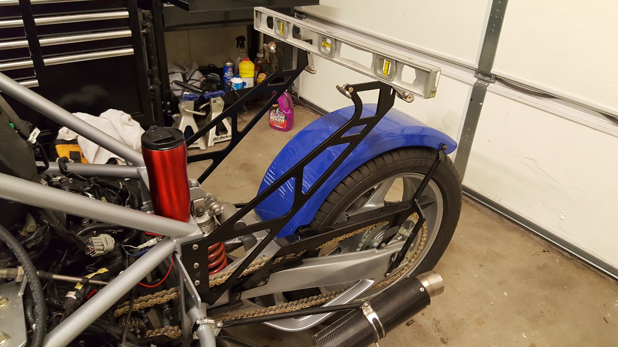 I started the process of installing the rear wing. The struts were easy to install. Just four riv-nuts on each side and a level and you are done... 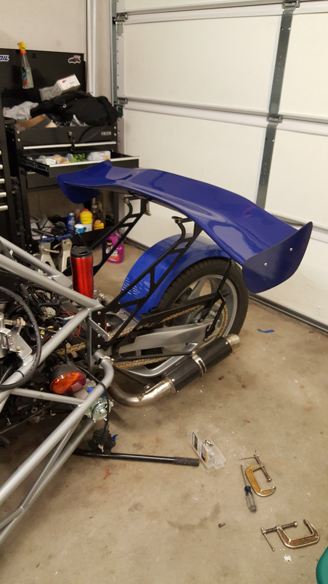 I have the wing sitting on the struts. The attach hardware took some reworking due to the odd angles in the lower side of the wing. The attach hardware appears to be stainless steel and I need to file and shape it a bit before I permanently mount it. The Garage is somewhat of a mess. Between being gone most of the early summer, then working on the house for a couple of months, I find myself entering the Autumn season and "STILL" traveling about. I am headed to California in about 2 weeks. When I get back, I will be going full tilt on the trike again. Summer is for riding, not wrenching... I did the rework on the wing hardware. It was a matter of putting a slight angle on a couple of mount tabs to compensate for the curvature of the wing. The kit came with almost everything to mount it. I furnished the riv-nuts and stainless bolts and Dove Racing's manufacturer in the U.K. Included the rest in the kit. It is quite solid and once mounted quite (impressively) rigid!! Bearing in mind, the canards and wing are not just decorative, but also functional. The wing is set to neutral effect, the front canards will be set for downward force by lifting the trailing edge of the canard (upward). I will set the angle of attack to maximum downward force, then adjust from that. If necessary I will also adjust the rear wing accordingly, but will leave it at neutral, or slightly angled to provide small amount positive pressure to the rear wheel. Like I said above, summer is for riding and having fun, fall is generally pretty decent riding as well, but as the weather declines, I tend to work on my projects more. I have switched to "FLICKR" to host photos. The program they use takes a little getting used to, but there are a lot of possibilities when it comes to saving photos, sharing them and photo hosting. I am not going to revive my ECO-EXO thread photos. The project is dead and looks as though no one will be manufacturing them in the near or distant future. Look for more posts here. I am going to be doing some finish work on my TR1ke to include clutch connection and brake bleeding. I am having second thoughts about wiring the neutral indicator Into the reverse circuit. I already have a red cover safety switch to prevent inadvertent engagement. I think I could see some value by engaging reverse with the clutch depressed and the bypass to "on" and pressing the main power button. That's about it for now. Roger Worcester, Massachusetts Yes I too think the ECO is done. I was wanting to step up and carry on with it but too many road blocks. It would be better if Stuart just came up with a NEW and simple design using more modern running gears than the 2002-2006 Carb Burgman 400. There are over 10,000 Burgman 650's and Honda Silverwing 600's out there.... But enough crying in my beer, don't like drinking salty Diet Beer. Dave... to be honest, the Eco-Exo does need an upgrade. If another attempt were made at its revival, it would be a good thought to make some improvements in the design as well as the engine. However at this stage it is even a mute point to discuss it, that's how dead it is LOL. Here is a suggestion and one worth considering. The Honda GL1500 and Valkyrie would be fantastic donors for a kit like the Tr1ke. The GL1500 has 100 Horsepower and 150 Nm (111 ft lbs) of torque. Compared to the Yamaha R1 2005 models 180 HP and 106.6 Nm torque rating. Of course the GL1500 reaches its 100 HP at 5200 RPM While the Yamaha reaches 174 HP at 10,500 RPM. It wouldn't be the rocket the R1 would be, but it would be a vehicle that comes with absolutely NO electronic issues. All models were carbureted and basic electronic ignition. In addition, most have built in reverse. It is a well known fact a GL1500 engine is good for over 100,000 miles, shaft driven and sufficient torque to drive the chassis down the highway at a respectable speed. The custom touch would be to add the 6 carbs from the Valkyrie, to a Goldwing engine that has reverse, some custom exhausts and a dark side tire.... who knows what might happen. To bad ESC caters to the high performance rocket sleds and doesn't realize the US market goes cross country, and with the Goldwing engine, it would make Almost bullet proof. In comparison, the Yamaha R1 is a wheel popping hot rod. It isn't all that great to keep all those ponys under control while in the stop and go city street. It is a go fast machine, high gear ratio, and of course carries a 13,500 RPM redline. The GL1500 on the other hand is made to carry a Middle Aged FAT rider, His Fat wife or better yet, fat Girlfriend, towing a trailer loaded to the gunnels with girl things, traveling between Boston Massachusetts and Los Angeles California and without a whimper. It has both the HP and Torque to go the distance. Just a thought ESC..... Anyway, that's my own idea and I really don't expect anyone to jump on my band wagon and start pestering Stuart Mills, or the current Makers of kit cars to come up with the design. However, It makes a lot of sense. Honda made the GL1500 from 1988 thru 2000 and never changed it much. Okay, I am done now. Roger Worcester, Massachusetts Today's efforts were to get some of the clutter out of the way in the Man Cave... aka garage. It is my last sanctuary, heck... my only sanctuary. Between my Mrs. cast offs, old paperwork, form letters and storage bins it's a wonder a guy can do as much as turn around and look where to put the rubbish before turning a screw. I think that made sense. Anyway, I combined all my project box supplies into one larger roll away job box. I need to sort out the trash from the good stuff in what remains. Okay, tomorrow I will finish the clean up and will install the canards on the TR1ke. My tools are mostly in the large roll away and somewhat organized. I can work with what remains after tomorrow. In yesterday's post, the one above, I highlighted section of it to get some interest or thoughts on installing the Honda GL 1500 engine in a modified TR1ke chassis. I have a perfectly good Honda Goldwing that has a 1500 cc engine in it, however I'm not about to take it apart and run the experiment. What I would like to do is get together a junk engine and swing arm. I could disassemble the engine remove the innards and use it as the basis to install into the Chassis. Perhaps waaaay down the road a ways. By the way, the distance from the bulkhead to the R1 swingarm axle is about 43 inches. The GL1500 is only about an inch or so longer from the engine front to the axle.. The GL1500 engine is heavier naturally. Anyway, fun to think about. When I get the canards installed, it will be photo op time. I will do a few and post them tomorrow if the light holds out for me. That's it for now.... I need to get a few 5/16" bolts before I get started. Roger Worcester, Massachusetts |
|
|
|
Post by roger on Mar 5, 2019 2:58:12 GMT -5
PAGE 11 Roger, The Goldwing topic could be a WHOLE tR1ke topic just by itself. If you follow the "Old Wing" forum, a lot of riders have fitted the older style Weber Progressive two barrel carb using a VW type 4 manifold. The 1200 cc loves this single carb, better gas mileage and bottom end torque with the same top end. This style carb from a 2000 cc Pinto/Capri on a 1500 cc should work too. That and the replace the (NASTY) stator and voltage regulator with a 1 wire alternator. And the newer "Wings" can have a Car tire fitted with some work. classicgoldwings.com/forum/viewforum.php?f=107 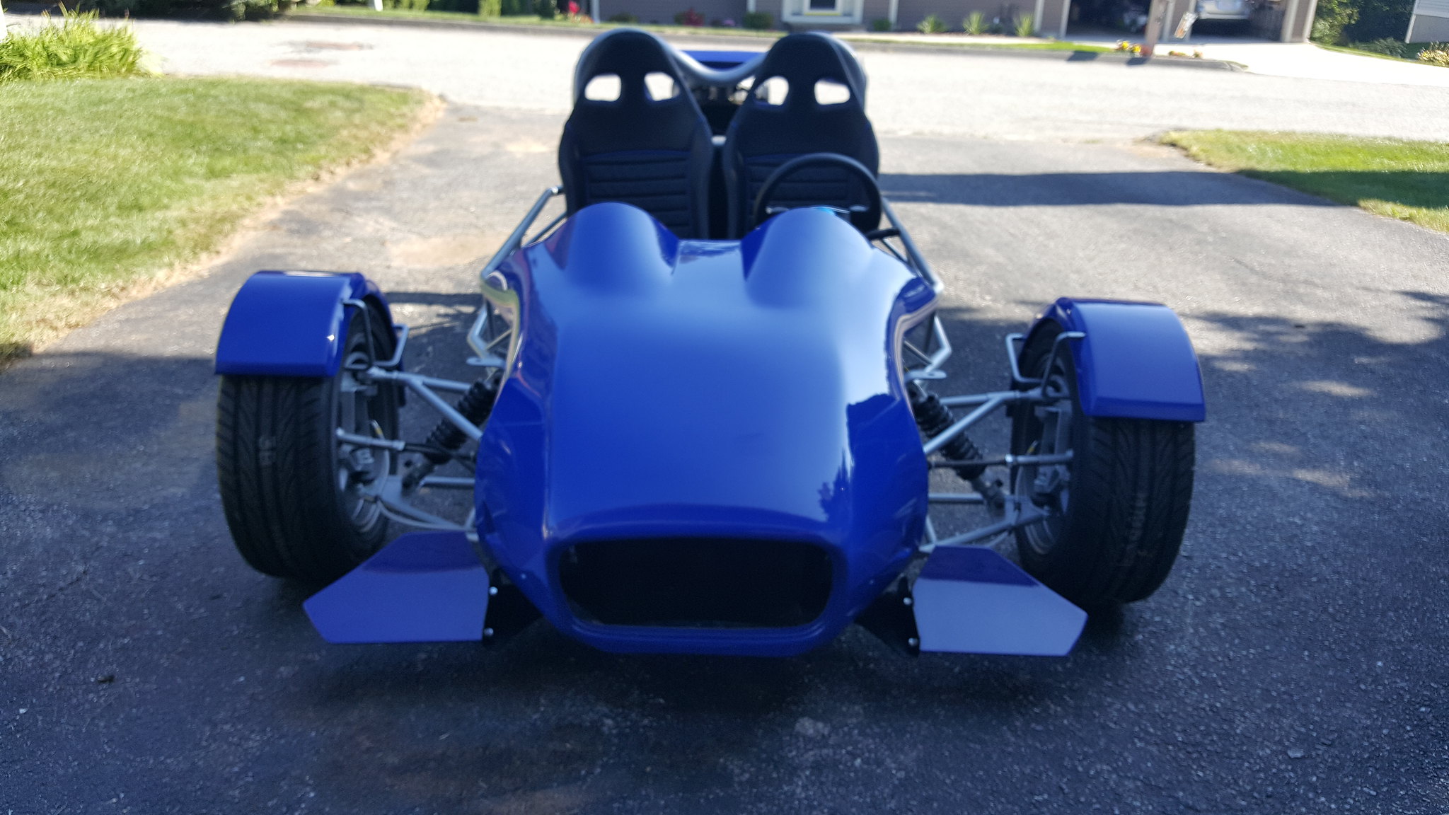 I installed the rear wing this past week and just installed the canards this morning. Looks pretty good. The good part about this is you do not have to make a mount point for the underside of the bonnet. The canard mount has a hole already drilled for this purpose. These are not only functional the look pretty BAD A$$. Roger Worcester, Massachusetts 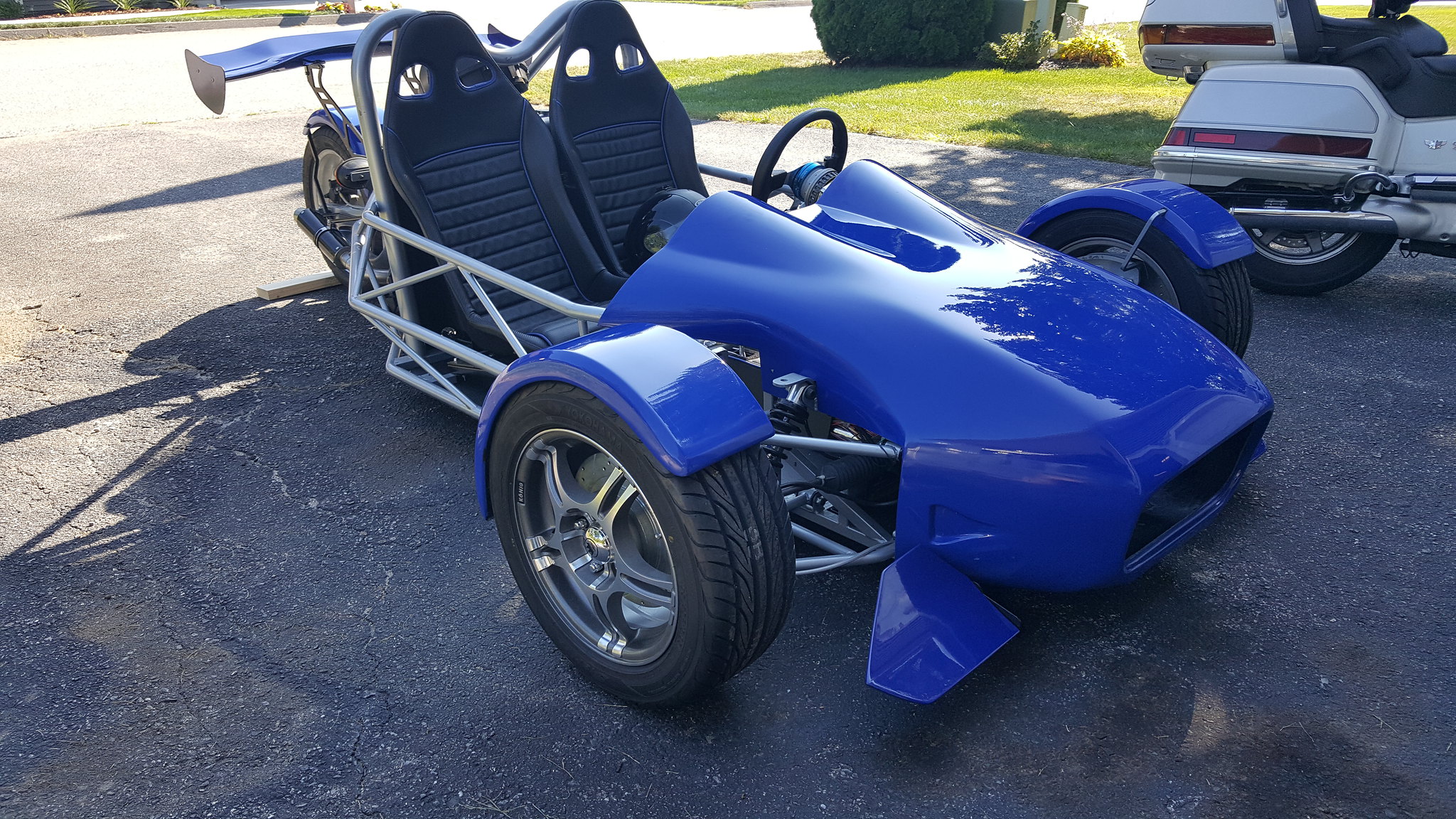 I took the TR1ke out of the garage and did a little spray polish and clean up after I added the Canards and Wing. Not a bad color of blue... and for those that noticed the seat sitting a bit to the right at the top on the Passenger side.... It isn't actually bolted in place yet... Roger Worcester, Massachusetts 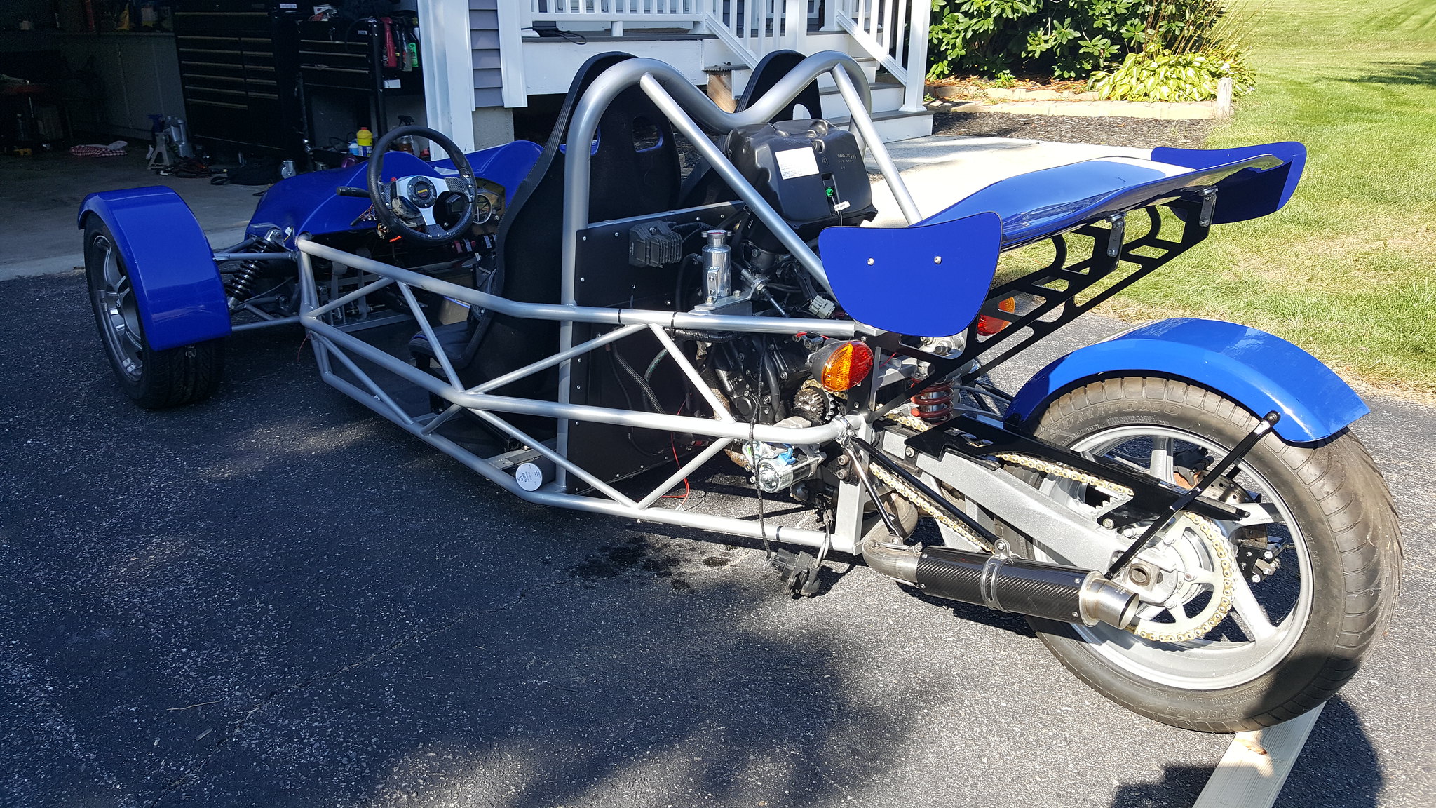 This is just another shot of the right rear. Although I have the wing solidly in place, you will notice the electronic piece hanging down that controls the exhaust baffle. Not exactly sure what the name of it is, but I do recognize the function. Anyway. There is a bit of work left to do. I need to remove the bonnet tomorrow and finish the electrical and brakes..By the way, notice there are no fuel tanks in the engine compartment. Both are behind the seats. Roger Worcester, Massachusetts 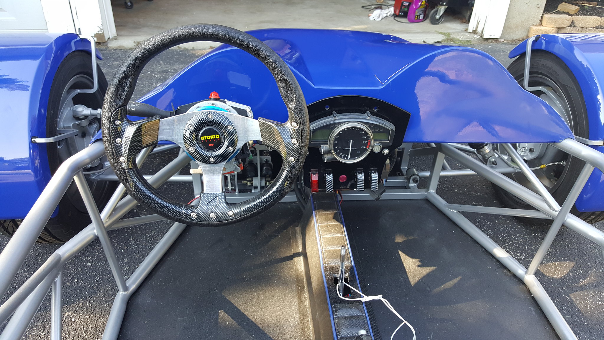 I mounted the gauges on a 1/4" piece of flat aluminum (or Aluminium) as you like. The switches are mostly for future use. I plan to install some fog lights, an accessory outlet and maybe a dedicated circuit for a dash cam. The covered (RED) switch is the safety for the reverse system. Roger Worcester, Massachusetts 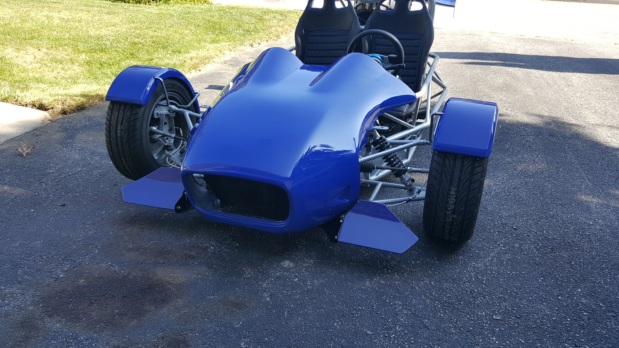 I really need to comment on the truly outstanding workmanship of the canards and rear wing. They are a great color match, and solidly made. I am not sure who made this set, but one thing for sure, the person knew their business. Dove Racing LLC, based in Trenton Texas, contacted the person on my behalf and got them for me. You may notice the headlights and front turn signals are not installed yet. I have a set of very nice Adjure lamps and a matching "NON ADJURE" pair of front turn signals. The signals look similar to the design but not the Adjure brand. I will be installing those in the next few weeks.. ... Probably after I get back from California. CHEERS Roger Worcester, Massachusetts 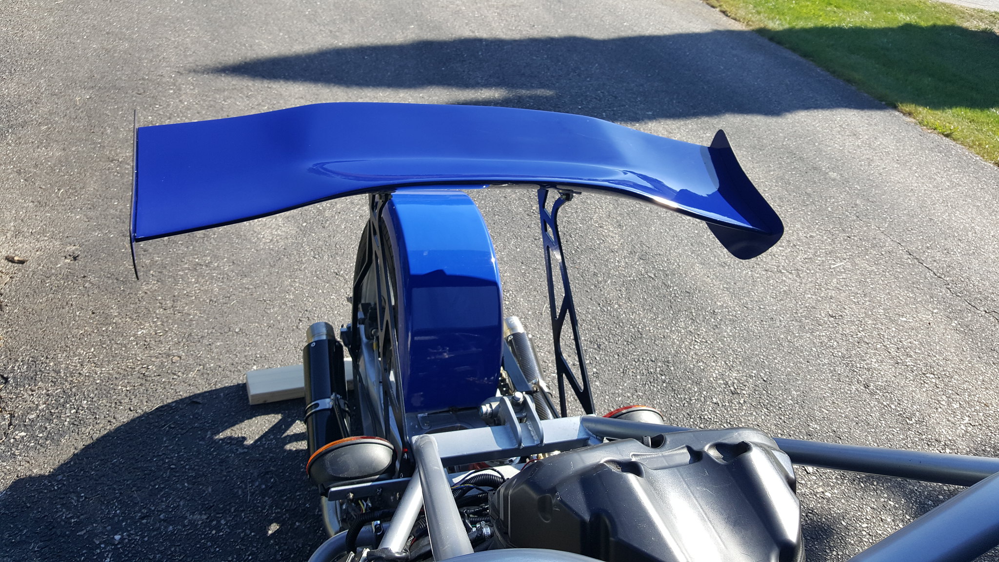 Last picture in the sequence. This is the only picture I took of the rear wing that is actually a close-up. As you can tell, it looks pretty decent. I am quite happy with the outcome. Roger Worcester, Massachusetts |
|
|
|
Post by roger on Mar 5, 2019 3:09:50 GMT -5
Looking good Roger. Did you ever get chance to weigh it?  Stuart: I did have a chance to weigh it. The weights were taken with no fuel in the tanks behind the seats, however you can figure about 7.7 USG placed in front of the fire wall. The two tanks are equally balanced. As it is, the weights were taken just as you see the trike in the latest photos, with canard and wing. I weigh about 105 KG So, without further ado: LEFT FRONT: 237.2 = 107.59 Kg RIGHT FRONT: 236.2 = 107.14 Kg REAR: 340.2 = 154.31 Kg I hope this is what you are looking for. The weight of my TR1ke is only slightly less than your calculation, but since I have gotten fat as a hog, and keeping away from the bacon factories, my calculations will be considerably different with me and a passenger. Roger Worcester, Massachusetts FOOTNOTE: I HAVE TO GET A FRIEND OVER AND HAVE HIM SIT IN THE TRIKE TO GET A LADEN WEIGHT AND BALANCE. I REALIZE THE RAW DATA THAT IS POSTD HERE ISNT ALL THAT MUCH DIFFERENT FROM YOUR POSTING ABOVE. MORE INFORMATION TO FOLLOW. Here is the updated information: Passenger seated weighs 204 pounds = 92.5 Kg. All weights taken with Passenger aboard, and fuel tanks empty Left front 332 pounds = 150.6 Kg Right front 332 pounds = 150.6 Kg Rear 395 pounds = 179.2 Kg Roger 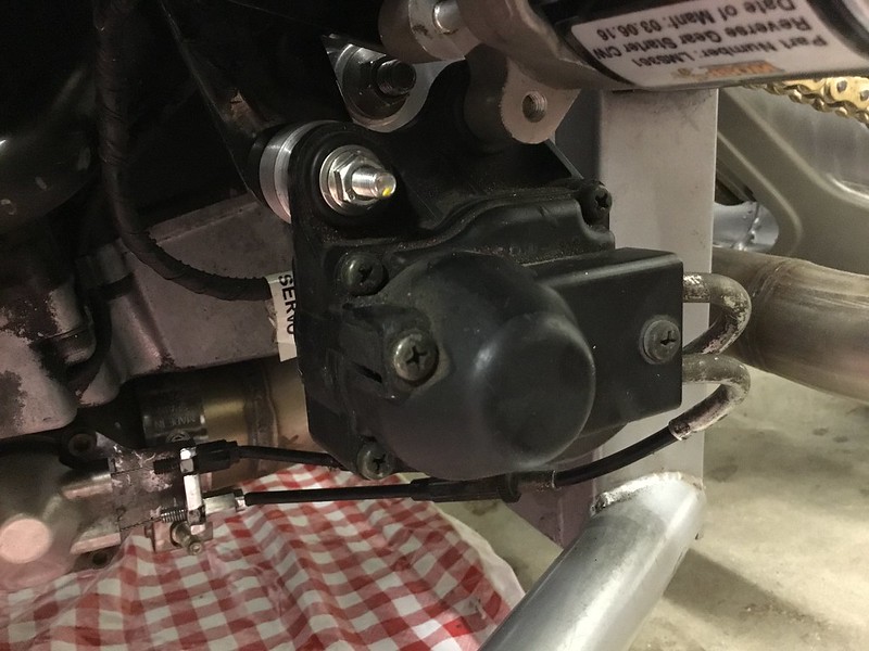 4 4I finally got the Exhaust Damper Controller mounted. It has been dangling from a wire since day one. The reverse starter motor had 2 perfect mounting points. There were a couple of 6mm X 1.0 bolts on the reverse motor that I was able to use. The rest of the stuff will be as easy. This was simply "one" of about a dozen more little tasks left to complete the build. When I return from California, I will be going full tilt in getting the remainder of the things finished and hopefully pushing it through the inspections system. Granted, this isn't much of a photo opportunity, but at least is shows progress. My next project is to mount the 4 point lap belt restraints, then I just "MAY" modify the shifting linkage from a cable to solid linkage with Rose/Heim joints at the end of the tubes. It all depends if there is sufficient clear space that allows this to be done. Thats it for now. Roger Worcester, Massachusetts Roger. Nice looking build! I just got mine registered this past week. I took 3 years to build mine, you have done much better. I’m still working out the bugs, but being able to drive my creation is more fun than I can put into words. Have fun. And be safe, Derrick Derrick Thanks for the post, nice to hear from you. I’ve been on this project since October 2016. I have been slowing down because I took the summer off and did some motorcycle touring out west. I managed to get the wiring and cooling systems in pretty fast, it starts and stays cool, doesn’t smoke and has good compression. The rest of the work is the usual stuff, lights, brakes, accelerator pedal and naturally brakes. Currently I am directing my attention inside the seating area and doing the finishing bits and pieces. I built an Eco-Exo-R a couple of years ago and drive that every chance I get. It is a lot of fun and I really enjoy getting out on it. I know what you mean by there is nothing like driving your own. I should have my TR1KE finished soon and ready for inspection. Massachusetts is VERY HARD to get a kit vehicle through the inspection system, but not impossible. I will be getting the paperwork and receipts together and building my folder to take to the inspection station. Anyway, thanks for taking the time to do the post. If you have a few minutes, post a few photos of your completed TR1KE, I would love to see it. Also, while I have you, any suggestions on the alignment settings? Roger Worcester, Massachusetts Roger, Good luck with the registration. I lived 37 years in Mass. I remember the DMV. I had trouble with registration here because I had 3 bikes and 4 motors and the motor I had in the tr1ke I bought from NJ. The numbers had been messed with so I had to install another motor. The rules here in AZ are very lackzed, but the DMV is still DMV. The alignment I used was old school torpedo level on the brake rotor for camber and I made a toe stick for castor, just means the front of the tires are 1/8-3/16 less than the rear. So they toe in. Seems to run pretty straight down the road. The guys in England use all kinds of math for this, but i’m old. My other motor is still at the builders, lower compression pistons from FZ1, double base gaskets ported and polished head. For this motor I have my supercharger runs 18psi of boost. Should make 240hp on pump gas then I have a 30hp shot of nitrous. I’m not sure the car needs all this as it breaks traction if you goose it on a straight away. I have a tough time posting pictures here I’ll try to pm them to you. Derrick: Things in Massachusetts have not changed much with the DMV since I moved here in 1987. My experience with them is to make sure that all paperwork and equipment are documented accurately. It took me 2 tries to get my Eco-Exo-R through the system. It was all because of paperwork. The salvaged donor engine needed the appraisal from the insurance company at the time of loss, and then the transfer of ownership form was filled out, but the form that was used was copied from an original even though the information on the form was original. I got off easy, I got the paperwork and it went right through, but “oh what a process”. I will look forward to the pictures. The supercharger sounds like sticking a rocket booster on an already fast car, but when you add NOS... holy cow, not much I can say about that. Sort of like “poking the bear” a bit. For me, I think the 180 HP will be enough. I would like to modify the intake air scoop for ram induction, but that will be after I get it through the system. I was 68 on my last birthday and I am aware of my age limitations... (like Dirty Harry). I would like to take it down the road and open it up once just to say I did it, but for me, cruising the mountains and the backroads here in New England is why I built a two seater. I don’t know much about the R-1 engine except the obvious, 180 HP, 13,500 redline, liquid cooled, that sort of thing. I would like to know how durable it is for the long haul. My donor has 25k miles on it, no leaks, some scars but nothing serious, and doesn’t smoke, no knocks, and no unusual noises. I am hoping it is somewhat “bullet proof”. Honda’s big boxer engines are made to go well over 150,000 miles and still give outstanding performance. This is partially because the big bikes are not made for the hot rod style rider. I would like to take the TR1ke on a long cross country, but there is always the worry of over working the R-1 performance engine. If It were an easy swap in, a GL1500 engine would be fantastic in this chassis. Anyway, I am back at working on my project. I got a few items finished yesterday and still at it today. It is nice hearing about all the performance mods you are making to your TR1ke. You are really running on the cutting edge of the power band. I have seen videos of other owners and their stock engines litterly light up the rear tire and lay a strip of rubber as long as they have their foot on the pedal. I am thinking mine will remain stock. I should be finished this season and on the road before spring, test drives coming up soon. Before I sign off, thanks for the old school alignment specs. I will be using the torpedo level as well. Roger Worcester, Massachusetts |
|
|
|
Post by roger on Mar 5, 2019 3:26:29 GMT -5
PAGE 12 The figures suggest that there is a front weight bias, maybe the wheel base is longer than 2600 , or maybe my maths is wrong. From watching tR1ke video's I noticed the swing arm angle change during acceleration as the rear of the chassis lifted. Maybe we should consider shifting some mass rearwards.  The figures that I provided are with only one person in the seat. I finally received my winter supply of pellet fuel (75 bags @ 40 pounds each) and I will use 4 bags placed in each seat, plus one bag in front of each seat, then re-weigh the trike. I will also do a measurement for wheelbase so the calculations will be correct for my trike at least. I have also noticed the rear end of the TR1ke lifting at the pivot point of the rear swing arm. My Eco-Exo-R does that as well. It is quite the opposite for my 1999 Honda GL1500. When I do a rapid “Jack rabbit” take off, the back end drops down, nearly bottoming out the shocks. Since the wheelbase is much more closely coupled on a motorcycle and the mass location largely depends on the rider and/or passenger weight, the result is predictable. Without some major engineering, how would it be possible to shift enough mass rearward on the TR1ke to change the CG moment. My Eco-Exo-R handles quite nicely even at high speeds, the steering is predictable and the suspension is quite adequate for this application. So, my WAG is that the nature of these extended wheel based vehicles using stock components for suspension will react as you have stated because mass is not acting as the applied force sufficiently to reduce the rear end from lifting when the vehicle is accelerating. If it were possible to move some weight to the rear, what benefit would be gained? I have not driven the TR1ke yet, but am very close to that mark. Of the kits that have been placed on the road, I do not know of anyone having an issue with it in this regard. As with any vehicle on the road, especially ones manufactured for the purpose of hauling a load, they are pretty forgiving when it comes to handling while fully laden, but not as good as when they are going down the road with no load at all. I would have to draw somewhat the same conclusion for the TR1ke, fully loaded, handling characteristics will change, but still probably very manageable. Needless to say when I get mine through the legal stuff and am driving it, I will be accessing its drivability until I feel comfortable with it. That should take a few seconds to figure out...;-) Lots to do to get ready for winter here. I need to wrap up some chores and prep for colder weather. I will get the weights posted as I have time. Roger Worcester, Massachusetts True, there is not much mass that we can push back. We do not sit over the rear wheel like the bike rear suspension was designed for. One way to improve would be to make a shorter rear swing arm with shocks mounted either side. Another is to heavily damp the rebound as shown in this short vid, we see the drag bike approach. Hope this helps. There are quite a few manufacturers out there. The rear shock I currently have on the TR1ke is an OEM , with a HEAVY wound EIBACH coil-over spring. I have a few options open to beef up the suspension from an anti-roll bar on the front to adding a dampened rear shock coupled with the EIBACH heavy duty coil over. I would like to have a functioning suspension, firm but not stiff, but not like I am riding in a cushy limo either. The entire experience of building a kit vehicle includes a certain amount of experimentation, calculation, and engineering to get things right.... or right for the owner and operator. When Edward VanBelkom set up his Eco-Exo-R he did extensive engineering on his trike and added newly designed “A” arms, and dampened coil over shocks manufactured to an exact length of travel to eliminate bump steer. He also contacted the folks at Hagen suspension and they made a rear shock for him. One thing about experimentation and engineering, it gets expensive especially when it comes to having a “one off” specially made. I used the front shocks that came with my Exo-Exo and the OEM rear from the donor. It handles great in my opinion. I will also use the suspension that came with my TR1ke. If it proves to be a problem, then I will take care of it by what ever means is logical and correct. Thanks for posting the video.... it would be nice to find out who made the rear shock for the bike. Roger Worcester, Massachusetts I went to Brock’s Performance website. They support the Yamaha R1 for a few product lines but I could not find any suspension components. Mostly exhaust. Wicked expensive stuff. It is either really good, or just over priced. Personally, I do not do the sort of riding that demands what Brock’s Performance sells. There are a ton of motorcycle related after market accessory suppliers, manufacturers, and custom “one off” builders out there. If In the future I need their assistance or their products then it is good information to know. For now, I will stick with OEM or a company like Hagon or Eibach. Roger Worcester, Massachusetts I ordered a piece of honeycomb pattern steel for my grill insert. It has a 1/2” pattern and allows 81% free flow of air. Once I get it molded and powder coated I will install it with either silicone adhesive or other means. Not sure just yet on how that will happen. I have my template made and will start this weekend. I also seem to have lost the electrical connectors I bought for the headlights and front turn signals. I had to order another set. I hate it when that happens. My wiring bundles and branch lines are all but tied up and secured. I ran a bonding strap from the battery to the front of the chassis yesterday, secured and mounted my relays and installed strain relief retainers for some wiring that was hanging a bit. I believe a battery box and a passenger side barrier panel may soon be in order. That’s about it. Things are coming together... Roger Worcester, Massachusetts As most know, most motorcycle manufactures do not use a chassis Negative Earth Ground. They use a return wire, usually a black with a white stripe in 18 wire gauge. Even the headlight wires are 18 gauge, should be 14 or 12 gauge. So adding a Bonding strap is always a plus. On your rear shock, there must be a Progressive or Hagon unit that can be modified to fit. On my son's Kawasaki Ninja 500, we got a Suzuki GSXR600's rear shock and spring and made the bush fit. On your Steel grill unit, you could weld on a couple of small steel flat washers before power coating. Then use small bolts to secure it. When I do the electrics on the trike it is necessary to modify the wiring harness. It is a popular practice for the manufacturers to use copper bands to stake wires together in the harness. Let’s face it, if you are looking for a ground, or a wire that has switched or in switched 12 VDC it is the best method. Essentially most harness use the same wire “mules” to Get this done. Sometimes there are 5 or 6 wires banded together on the same mule. When I do my wiring, I clip these banded wires and install a circuit buss or a chassis ground point. Currently I have an oversized Eibach coil over an OEM rear shock. This should take care of overloading the rear and aid in preventing a “bottom out” situation. Getting a beefy suspension is not always the best answer. Rebound dampening is something to consider as well. Currently I will use my shock that is already installed. It is a starting point. I really don’t want screw heads sticking out front of my grill surround. Since I will be doing some extruded metal molding, I will have a small flange in which to anchor the grill. It will be okay with the clear silicone adhesive.. I finally made the passenger barrier wall, the one in front of the passengers feet.. I need to round off the edges and corners and take it to the powder coaters along with my grill and the battery box. Should be able to do this on Monday. I have the battery box all cut out and just need to go over to my friends place to use his bending brake. After all this comes the polished diamond plate foot rest... Well that about all for now.... Roger Worcester Massachusetts |
|
|
|
Post by roger on Mar 5, 2019 3:31:14 GMT -5
Today I got the battery box completed with the exception of powder coating and the retaining strap. I made the box large enough to slide in a plastic insert for padding. Tomorrow I will make the grill insert and trim the excess off leaving a 3/4” flange around the perimeter where I will apply the adhesive. I might install a pair of hidden mini driving lights. I provided for them in my electrical layout so why not?? I need to do another clean up and sweep some of the fall leaves from the garage bay, put some tools away and start shelving the remains of my working stock. It’s funny, I don’t mind making the mess, but the clean up... well, that’s another story. The trike is nearly ready for inspection. I need to “dot the I’s and cross the T’s double check everything then trailer it to the inspection station.... well nearly so. Still working on some of the bits and pieces but nothing to serious needs doing. I will be posting a few pictures of the stuff beneath the bonnet, like the wiring, battery box relays and other stuff there. I need to get the wiring connectors installed for the headlights and front signals before I take the pictures though. The connectors are in the mail..... That’s about it for now... Roger Worcester, Massachusetts Just a fast couple of lines. I picked up my parts at Central Mass Powder Coating, the grill, battery box and the lower barrier between the passenger and the radiator. All were very nice. I installed the honeycomb grill in the bonnet and have it at the paint shop getting a nose job done. What I will have is a silver grey nose with a centerline stripe extending back between the cowl “humps” on the dash. It will need the edges pin striped but will get that done this summer along with some detail work on my fenders. As far as the other two items, battery box and barrier go, they will be installed tomorrow. Pictures to follow. I am about finished with everything. If tomorrow is a nice day, I will install the electrical connectors for the front signals and headlights. Next after that is Adel clamps for the brake hoses then fill and purge the system. The inspection system will be there waiting, so no rush to get it done prematurely. Anyway, that’s it for now. Roger Worcester, Massachusetts 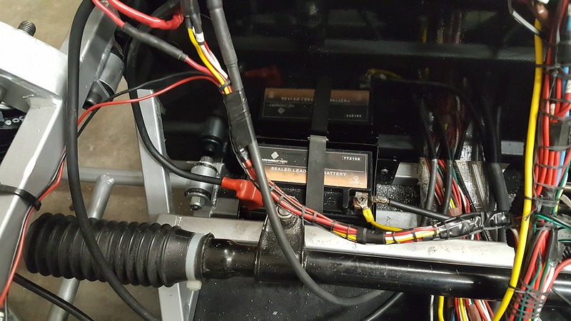 Not a lot to see. The battery box and passenger kick panel have been installed for fitment. I drilled and tapped the mounting locations. What I need now is some double sided tape that Eddie from Wisconsin is sending me. Once I apply that tape, it will be permanently installed your sure. As you can see, I have a lot of drill tailings on the floor pan, I have a Hoover just for that job and I ain't afraid to use it. Roger Worcester, Massachusetts 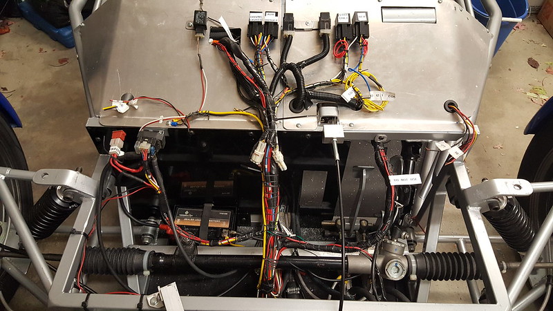 This is generally the layout of my forward electrics. It isn't quite at 100% yet. I want to put a couple of hundred miles on the chassis before I do a complete wrap job on it. Don't want to slice off the sheathing to make a splice or repair. I am a big fan of labels during assembly. I keep them in place until I am confident enough to remove them. Which might be "Never" in this case. Again, the drill tailing's need to be removed and the general area requires some tidying up. If you look hard enough you may even find an overlooked spanner or other tool laying in the fray... Anyway, pressing onward toward completion. Once I get my bonnet back from the paint shop, I will push the TR1ke out of the garage and take a few snaps of it with the new silver nose and centerline stripe. Until later, have a great remainder of the week and weekend... Roger Worcester, Massachusetts I'd never looked real well at the chassis before. Square tubing? Looking good so far but your work area is a mess. Most of the chassis stock is round, the nose is square as well as some areas in the back. I agree, the area I just worked in is in need of cleaning up. I was going to do that today but needed to get some outside work done first. The leaves have overtaken the yard and I needed to clear them off and put them at the curbside so the cleanup truck can pick them up. Now it’s dark and cold, so will do it tomorrow after I do the headlight wiring. I should get the bonnet back from the paint shop next week. I should have most of the stuff done so I can bolt it in place after it is completed. For right now....... I am doing things as I have time for. I still need to get ready for winter, store my motorcycle, and haul out the snow blower. Ah, such is life in New England. Roger Worcester, Massachusetts |
|
|
|
Post by roger on Mar 6, 2019 1:16:54 GMT -5
PAGE 13 I am happy to report the headlights and front directionals have been hooked up with water resistant connectors. Easy on and easy off. I need to connect a few other wires and the process will be finished. I’ve been busy preparing for the Thanksgiving holiday but managed to get my garage somewhat cleaned up and my tools put away. Ed in a Wisconsin sent me some super strong 2 sided bonding tape. I completed the installation of my lower kick panel using it. It is every bit as good as I’ve been told. The bonnet is still at the painters shop and should be ready before Thursday if all goes on schedule. No one there does any pin striping, but that will be after the roadworthness inspection. I really need to start walking around the trike with a pad and pen to log items I may have overlooked. Just as soon as you think you have it all, you find something that was left undone. In short, run a punch list. That’s about it for now.... Roger Worcester, Massachusetts 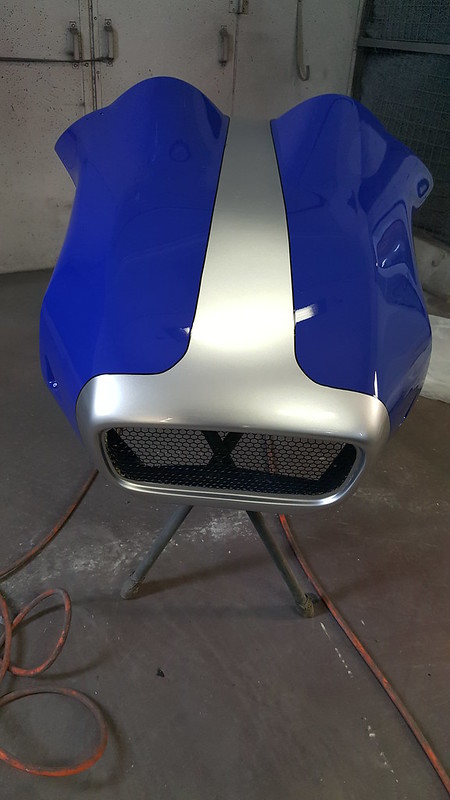   Attached are a few pictures of my newly painted bonnet. I had the silver stripe and nose job done before the Thanksgiving holiday and just got it back today. I also had the entire piece clear coated and polished. I will be taking the canards, front fenders and rear spoiler to have them clear coated as well as some touches of silver added. I still need to do some work to the under bonnet area, mostly just some wiring and fill the brake system. Anyway, here is what the paint scheme will look like. Roger Worcester, Massachusetts It won’t be long now. Once I start the front alignment, I will remove the other GRP pieces for clear-coat and the silver paint touches. I don’t want to remove the fenders until then, it is somewhat of a PITA to do. I actually need to weld the nuts to the fender braces so I don’t have to buy special tools like a crows foot to remove them. I will be finishing the electrics this week and hopefully filling the brake system in that as well. There are always the small touches that need to be taken care of but that’s all a part of the maintenance and repair of a kit vehicle. I know my Eco-Exo-R has not needed anything except routine maintenance since I did the modification to the electrical system.... but it did need the electrical mod. Not much else to say except I am still actively working on my project and even though it is going at a slower pace. I am taking care of the details as they come up. My Punch list is getting shorter and things are coming along quite nicely. Until later.... Roger Worcester, Massachusetts great paint job, love the black pin stripe Today I sorted out the rest of the wiring beneath the bonnet with the exception of the brake light connection. I do not want to have all of my accessory outlets in place just yet. No sense in having all that inspected too. I will have just the required amount to operate the engine, lights and indicators on the speedometer. The remaining items are the license plate bracket with light, fill and purge the brake system, alignment, then run my punch list to verify I have it all completed. Reverse works great.... quite strong in fact. Well, that’s about it. The bonnet will be the last thing I will install, then get the inspection done... With that, catch you later Roger Worcester, Massachusetts While giving a demonstration of the reverse system to a friend I find it is equipped with quite a strong motor. I actually backed into the aluminum garage door. Nice little “THAWK” in the general shape of the rear tire in the insulation of the door. It does prove that it works. It was a busy day today with other things. Car to the shop, fall clean up crew came, two appointments and now the carpet cleaners. Yes, we are getting prepared for a medium sized house party. My wife’s work associates and colleagues. Tomorrow, I will solder in the brake light wires to the pressure switch on the master cylinder, fill and Bleed the brake system and then connect the clutch switch. When I finish those tasks, the bonnet goes on for good and then I will make the rear license plate bracket and mount the light... I may reorganize some of the connectors on the engine but not unless it is absolutely necessary. Anyway, that’s it for now.. Roger Worcester, Massachusetts Okay, another update. I soldered in the connectors for the reverse push button on the gear box lever, as well as the brake light switch on the master cylinder. I also finished the rear filler piece that covers the space between the air filter housing and down the angle supports to where the license plate mount will be. I still need to drill and tap the lower area and then powder coat the assembly. I am not sure if I want to mount a license plate bracket to it or not, but for sure the tip over sensor will be attached to the inside. My wiring is secured, the brake bleed will be absolutely last. I have about 4 places yet that I need to secure the brake lines with “Adel” clamps... it’s looking like it may be able to get off the ground..... figuratively speaking of course. More to come later.. Roger Worcester, Massachusetts |
|
|
|
Post by roger on Mar 6, 2019 1:22:56 GMT -5
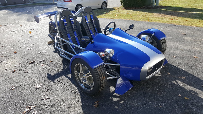 I finally got the TR1ke out of the garage and took some photos. With a few exceptions, it is nearly ready for inspection. After the holidays...  8 8I do not have the steering yoke cover on yet not do I have the tunnel cover on. Minor stuff. This is the general layout I chose for the drivers compartment. The start button is between the switch and the reverse cutout is the one with the red cover. If you look at the gear selector, it also has a red button. That is the reverse engage switch. The sequence is, Place the gear selector to neutral, flip the red covered switch to the up position, then depress the gear selector button.... I may eliminate the neutral selection later. Seems to be a little complicated to put it in reverse. Just don't want to tear anything up by accidentally engaging the system.  I am working on the filler panel to cover the back side of the engine bay. The inside will have a 6 x 6 inch reinforcement to mount the license plate holder. I am still working on this piece and the license plate holder is designed to clean up the rear fender on the sport bikes like the "R1" Yamaha. The piece should be in the mail box on Monday December 11th. Here is a picture of it below.   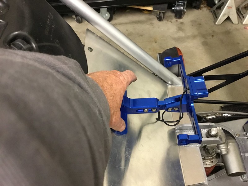 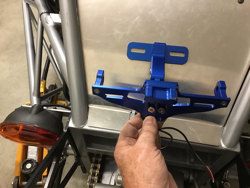 I Modified the license plate holder so it would fit the angle of the aluminum engine cover. I basically removed the attach plate from the license plate holder (with the slotted screw points) and milled off the surface 90 degrees to the original mount, then drilled and tapped with 10x32 threads. The piece is adjustable so I can easily make corrections if needed. Now I need to drill and tap the bottom of the engine cover then then go from there. Roger Worcester, Massachusetts I finished fabricating the engine cover panel. It is at the powder coaters. I chose a semi-gloss Black to match the air filter housing. There are 3 pieces total, a 1/4” stiffener block and I also added an attachment point for the tip over sensor and the humidity?? sensor. It is supposed to be ready by Friday.... just as well, have a root canal scheduled for Wednesday. Yea, my Little December surprise. Once all that is installed that will leave the alignment and brake system filled and bled. Roger Worcester, Massachusetts |
|
|
|
Post by roger on Mar 6, 2019 1:32:57 GMT -5
PAGE 14 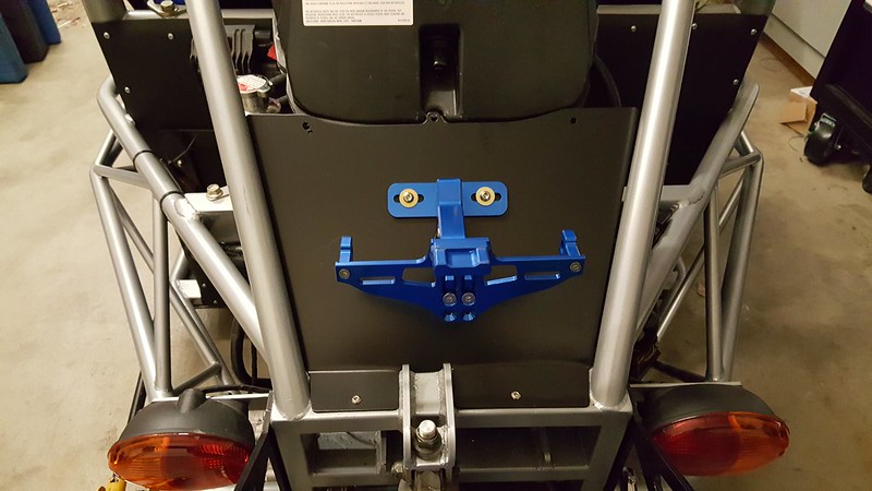 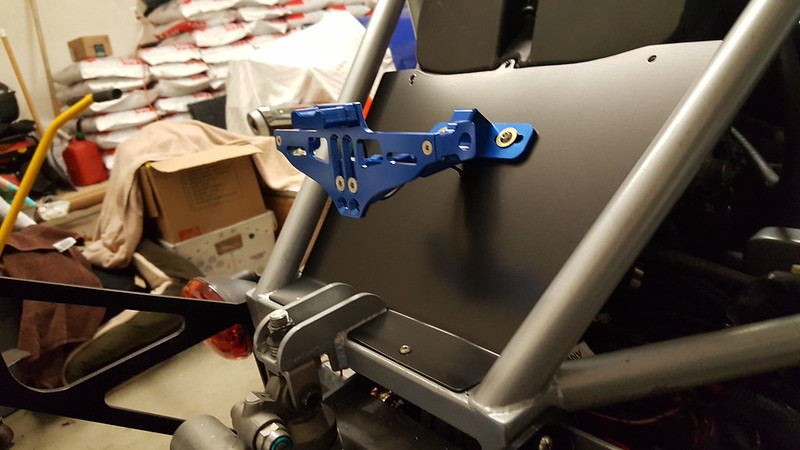 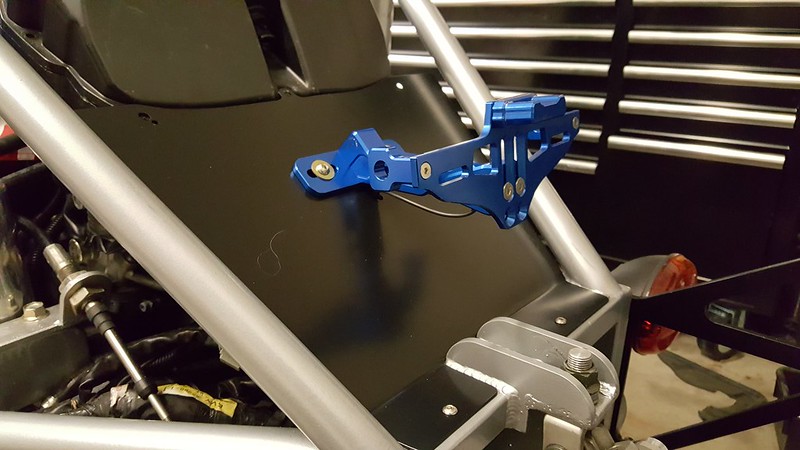 2 2I retrieved the panels from Central Mass Powder Coating today. Beneath this outer cover, there is a 4 x 6 x 1/4 inch stiffener block and a piece of aluminum to hold the tip over sensor and the humidity sensor.... (I am hoping it is the humidity sensor). I had the entire lot done is satin black. It matches the air filter housing and makes the blue license plate holder more visible. The plate holder is very rugged, and as I mentioned before, and is very adjustable. I will be adding an electrical connector for the LED license plate light, and I need to drill two more holes in the inner support to mount the sensor. All of the holes line up and of course you can see where I miscalculated my measurement. It isn't a total loss the screw head covers the error and with it being black, it is doubtful whether it would all that noticeable anyway. I have to keep in mind this TR1ke is a driver. I will ride the paint off the GRP... Whats the old saying, "Ride it like you stole it".... Well, I am a firm believer is keeping the engine hot, the tires worn out and the finish always needing a stop at the wash rack.... This will be in the next Veterans Day Parade 2018. All that said, I managed to fill and bleed the brakes yesterday. I have not checked the pedal travel so far today. I will tomorrow. When I finished, the pedal was high and the feel quite firm. When I bled it, It was just me doing it. I had to pull a vacuum at the bleeders and suck the fluid all the way through. After that, I pumped the brake pedal and fastened a tube to the bleeders and used a plastic water bottle to catch the excess brake fluid. Anyway, the punch list is getting down to the alignment and a few odd bits and pieces.... More to come. Roger Worcester, Massachusetts Okay, Christmas is next week. I will be putting a chalk line on the garage floor and centering the TR1ke on it for alignment process after Christmas. The rear section is done and the brakes work great.. at least all three wheel cylinders function. No leaks either... all is nearing the end but again, I am not wrenching on it every day. As things progress, I am constantly looking over all the other maintenance items and assemblies to insure if anything fails it won’t be catastrophic. It would ruin my day if I did significant damage to my trike by overlooking something as simple as not installing a split pin or cable tie down. So, today, nothing really new... I sent out Christmas cards with my Eco-Exo-R and TR1ke pictured on them. I will see about scanning one to post a seasonal greeting. Until Next Time Roger Worcester, Massachusetts  Merry Christmas and a Happy New Year Everyone... 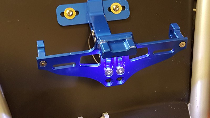  Just installed the electrical connector for the license plate light. It is quite bright and will light up the number plate all to well. Maybe to well.. Hmmmm!!!! Well, anyway, it is complete and all the connections, screws and hardware are secured beneath the panel. Next is the alignment... I am sort of dreading the procedure, but feel I am up to it. Sometimes I feel like a blind man finding his way through a room full of broken glass and razor blades..... I'll make it, but not without a bit of trial and error. To all those that celebrate the Christmas holiday, Merry Christmas, and to those who do not... Merry Christmas anyway... Tis the season of peace...Love and Charity. Roger Worcester, Massachusetts Awesome build!!! I noticed that you were able to convert your steering hub so you can have a standard 6 bolt hub on. I would love details on that as I would like to do the same. On the LED being too bright you could find a simple voltage regulator or build one using a LM317 transistor and some resistors. Or try a 12 volt USB adapter as the output will be 5 volts DC and it should drop the brightness down. I am Danish American and this year I have been following some Danish Christmas traditions. But I could not find any Akvavit Schnapps so I made a 1.75 Liter bottle using Vodka and anise seeds. Very tasty. So Happy Christmas and Merry New Year to all. (Hickup, burp) Glædelig jul og Joyfull nytår. OR you can get electronic LED dimmers for DLR lights - about £1.50 from ebay. They flicker the light faster than your eye can see... |
|
|
|
Post by roger on Mar 6, 2019 1:41:24 GMT -5
Awesome build!!! I noticed that you were able to convert your steering hub so you can have a standard 6 bolt hub on. I would love details on that as I would like to do the same. 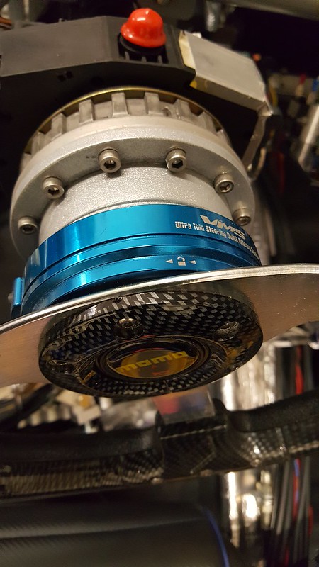 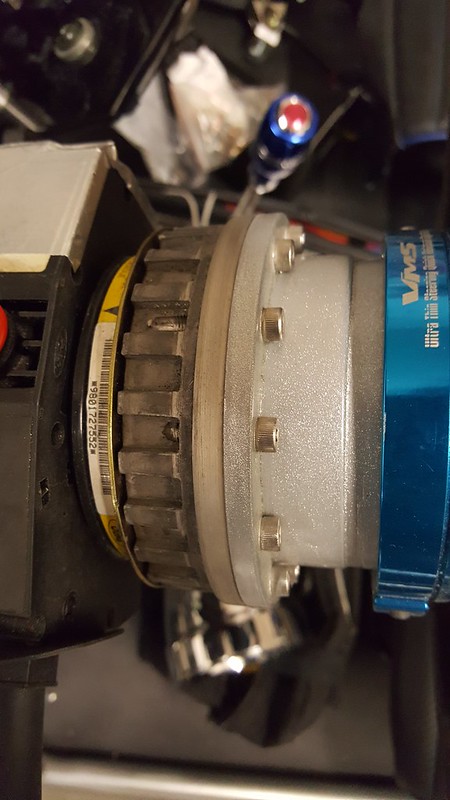 What I did to make the steering hub was to cut the metal part out of the OEM Ford steering wheel. I used a right angle grinder with a cutting wheel. I removed all the surrounding plastics and was left with a metal piece that I repurposed as the steering hub piece that mounts to the column. It is important to say that I have a lathe and milling machine. I chucked up the Ford hub in my lathe and turned it smooth, removing all traces of the spokes. This left a suitable mount for the steering adapter. I bought a 3-1/2 inch section of aluminum pipe/ tubing with a 1/4” wall. (I used about 2 inches of it) I had a local fab shop weld a 1/4” x 4-1/2” aluminum round disk on one side of the tube, then weld the other side completely closed using a 3-1/2” x 1/4” aluminum disk. I have an index system on my lathe and indexed 12 mount screw locations for the Ford hub to mount to the aluminum adapter and also indexed the 6 screw locations for the steering wheel quick disconnect. What I had to do was do a series of test fits to make sure all this would work as a unit. Bear in mind, The Ford steering wheel metal is not made of aluminum. It is WHITE METAL and you cannot weld it. After a few cuts here and there and about four trips on and off my lathe, the adapter was finished. If you look at the locking pawl catches on the Ford Hub you can see where I drilled through. It isn't the neatest look but will be covered by the plastic housing. I also was able to use the horn wiring and mounts. So it’s all good. Hope this helps Roger Worcester, Massachusetts OR you can get electronic LED dimmers for DLR lights - about £1.50 from ebay. They flicker the light faster than your eye can see... When I get back from the trike and look at the lights, it is somewhat of a light show. The blue of the rear fender and the absolute white of the license plate light makes a neat looking glow. Since the plate holder is adjustable, I will more than likely change the angle of the plate as not to flash anyone with the LEDs. It is quite bright, and a very white light. If indeed I need to dim it, I will more than likely do it by adding the LED dimmer. Roger Worcester, Massachusetts Thank you for your help. I do not have a milling machine so I will have to find another way. I bought a Momo adapter through eBay. I strongly suspected it was a fake, just like my Sparko knockoff steering wheel. The adapter didn’t fit. It was to large and slipped over the steering shaft but wouldn’t tighten down because the hex pattern on the adapter was to big for the shaft. I sent it back and got a refund, and decided to make my own. One of the reasons I wanted to make my own was I could keep the steering wheel lock. The other reason was that I initially thought the Momo hub was authentic, and ordering a replacement would result in the same fitment issue. eBay, in the past, has been a respectable source for hard to find parts, however it has become a haven for bootleg and pirated brand names. It seems this is okay with the eBay community. It is cheaper to refund your purchase than to regulate the sellers. I will make what I can and buy what I cannot. Roger Worcester, Massachusetts To be honest, my momo one didn't come from ebay, I just couldn't remember where and the point remains - you can buy one off the shelf - BUT where's the fun in that? I, like you, tried to make my own, adapting the focus wheel - partially as I don't have particularly long legs or hands, yet don't like the steering wheel too close & was also concerned about reach to the stalks. However without the proper tools (lathe like you have) it proved too challenging. One thing I will say though, is steering lock still works, as does self cancelling - its on the column not the wheel/adaptor. My "Momo" steering wheel on the other hand is a total fake - in a style they have never done as far as I can tell  The steering wheel on my Eco-Exo is a bootlegged Sparco, the steering wheel on my TR1ke is bootlegged as well. It is Momo branded. I will be buying a better one for the TR1ke eventually, but for now the faux Momo will be used. The steering lock relies on the OEM wheel to function, but not sure about the self cancelling directionals. It has been a year since I made it. I got a real good deal on my lathe a few years ago. It is an Atlas 1042. It was made in the 1940’s. The old stuff is often the best stuff. Trust me, I am not a machinist, more of a metal butcher. At best what I make works, but all to often It takes more than one try to get a satisfactory result. I am however, improving.. there may be hope..... :- ) Roger Worcester, Massachusetts |
|


 .
.