

Post by Admin on Nov 29, 2018 15:31:28 GMT -5
Vehicle Engineering (Visualized)
captainamerica
Exalted Member
Posts: 328
Mar 6, 2012 at 10:09pm
Post by captainamerica on Mar 6, 2012 at 10:09pm
Hi all,
This is the start to what will hopefully be a helpful suspension design thread. At some point it may expand to general trike design but for now I am going to concentrate on just the suspension, and more specifically the double wishbone layout. I will be incorporating lots of pictures because I myself am a visual learner and I feel that words can not do justice in explaining mechanical systems nearly as well. Please inform me of things that you like or dislike, so that I can make edits and changes for future posts. If you see something wrong or something I have missed, please point it out. Enjoy.
-Andrew
So first off is the basic suspension layout used on pretty much every modern open wheel race car in existence, barring formula Vee maybe, and a lot of the reverse trikes on here. The system consists of one upper and one lower A-arm (named for their distinct shape). These arms are used to attach the wheels to the chassis. Unequal length arms are used to keep the wheel relatively in the same position with respect to the ground no matter what the chassis is doing.
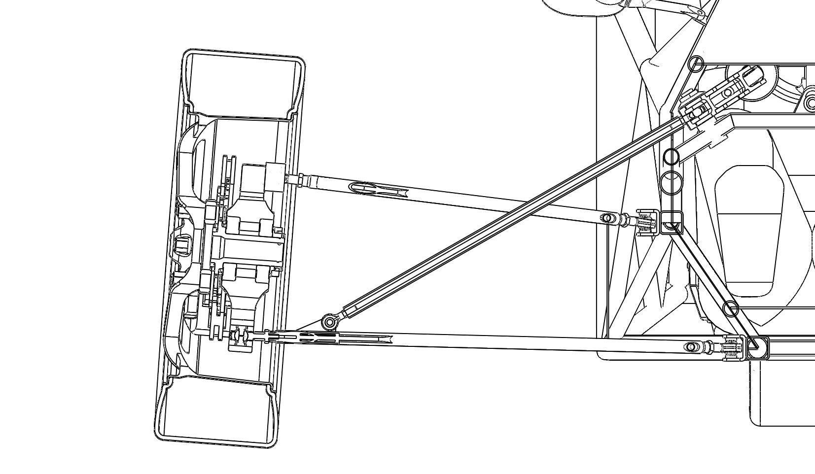
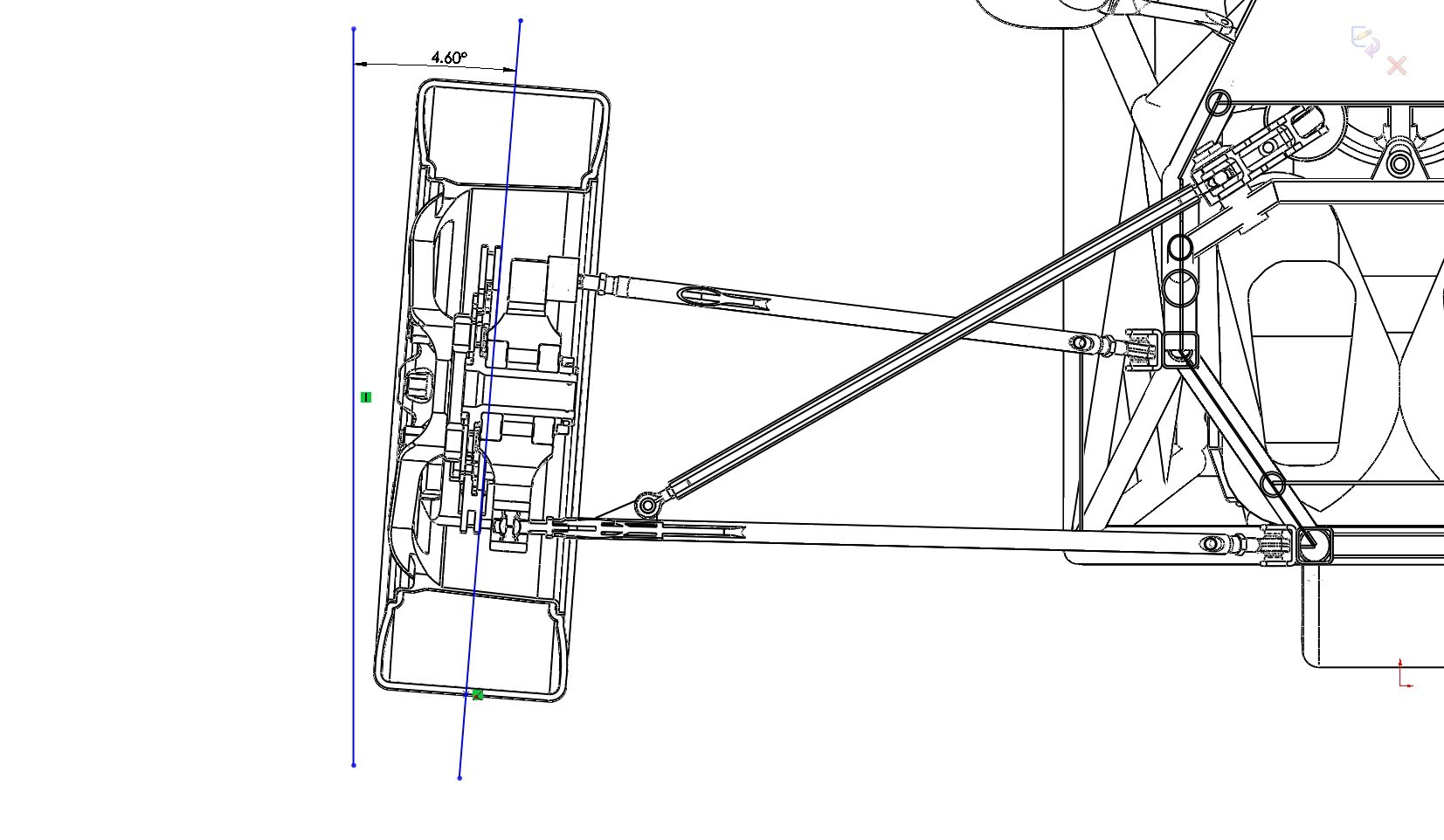
This brings us to our first term of the post, Camber Angle, this is defined as the angle the wheel makes with the ground. Camber is broken down in two parts, static and dynamic. For now we will only consider static, because that is what I have a visual of. When the top of the wheel is closer to the chassis we call it negative camber and the opposite sign is used in the opposite direction. In this picture the wheel is about 4.5 degrees off from the vertical towards the chassis so this would be negative (-4.5) degrees of static camber. Static camber is measured when the vehicle is static, preferably wet (fuel, oil, coolant) and with the driver on board. Negative camber is preferable for the same reason we lean bicycles when turning them at any decent speed, it makes the tire "dig" into the pavement when a horizontal side load is applied. However, if you have to much angle on a light vehicle you will actually lose traction in the corners (and in the straights) because the tire contact patch becomes too small. Another downside to incorrect camber angle is that you will wear your tire tread abnormally, I was running to much on the Spartan when I first built it and within 100 miles I could see a difference between the right and left sides of the the tires. Camber Angle is an adjustable quantity, altered by changing the length of the A-arms, usually the top A-arm as this is not linked to the pushrod so it is less complicated.
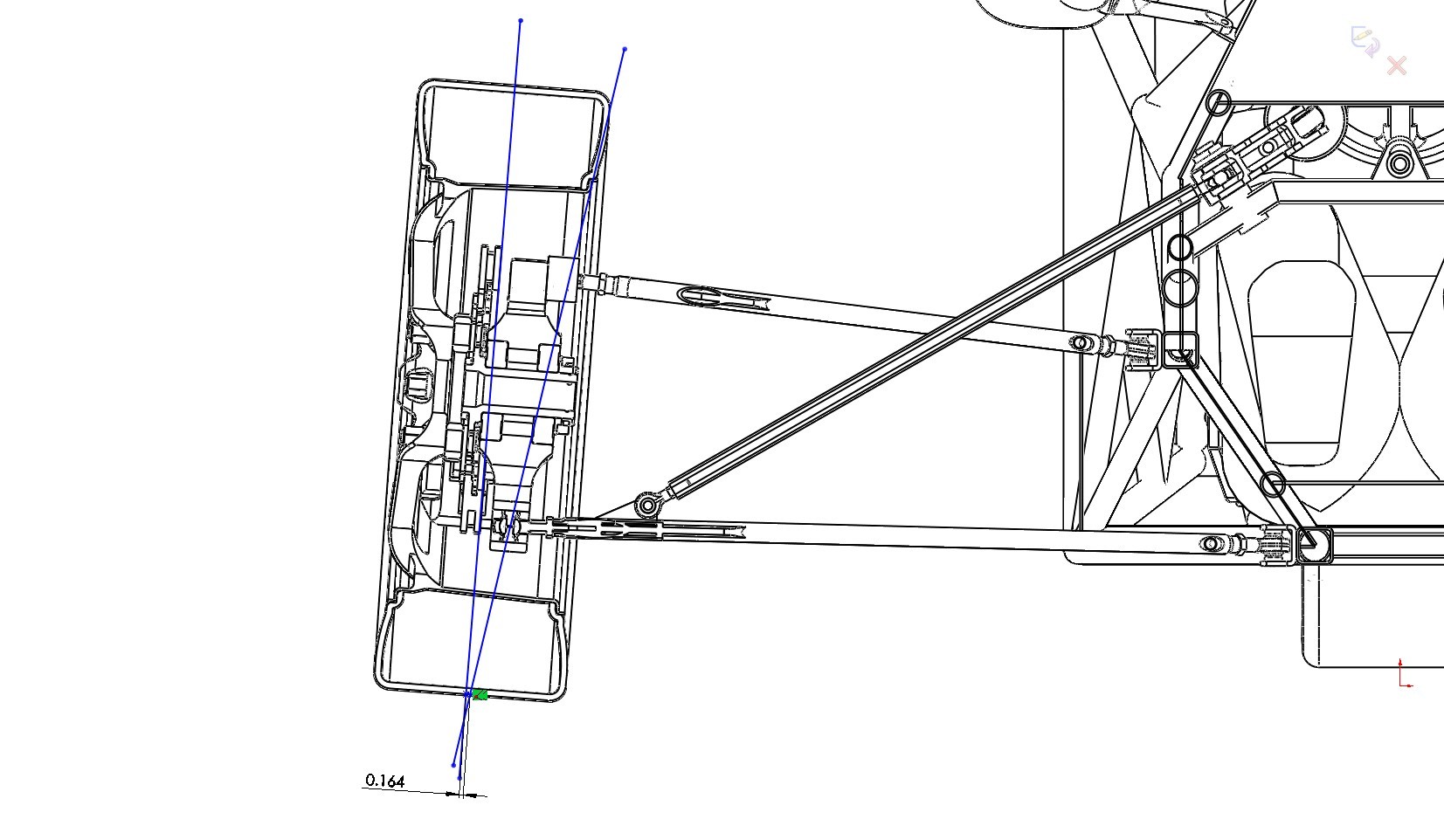
The next important term is Kingpin Inclination Angle and Scrub Radius. Simply put Kingpin Inclination Angle is the angle between an imaginary line drawn through the outboard A-arm mount points, looking from the front view, and the Camber Angle line. Some of you are probably wondering why it can't just be parallel to the camber angle, it very well could be but read on. The reason it is inclined relative to the Camber Angle is because the wheel actually rotates on the Kingpin Inclination line. The distance from the center of the bottom of the wheel to the point where the Kingpin Inclination line crosses the the bottom of the tire is a measured quantity called Scrub Radius. Why is this a radius and not a distance you ask, from the top view it is the radius that you have to drag the wheel around when you turn. For us visual folk, hold your hands out in T, as if your calling a "time out", with your left hand fingertips pushing into your right hand palm and your thumbs vertical. Now try to rotate your left wrist around the axis your left thumb creates while keeping the T shape. In this case your right hand is the tire and your left hand is the scrub radius. This is how the tire will move if your Kingpin Inclination angle is parallel to the Camber angle. This radius (the length of your left hand from thumb to finger tip) is known as the Scrub Radius because you are literally "scrubbing" the ground with your tires as you turn. The larger this radius is the harder it is to turn and the more you "feel" the steering system at speed. For those of us without power steering, this is a bad thing at low speed. The scrub radius in the picture is .164". Kingpin Inclination and Scrub Radius are design features of the suspension and are unchangeable without physically changing parts (usually by shimming one of the upright suspension mount points; upper, lower, or both). The design in the picture is capable of being shimmed on the upper mount only, and beware shimming at a mount point will also alter your camber angle so both need to be adjusted at the same time in that design.
Last Edit: Oct 1, 2014 at 8:31pm by captainamerica
Mar 7, 2012 at 12:34am
Post by captainamerica on Mar 7, 2012 at 12:34am
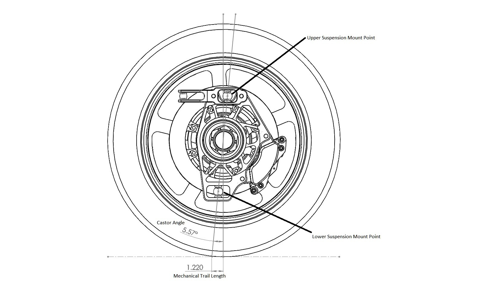
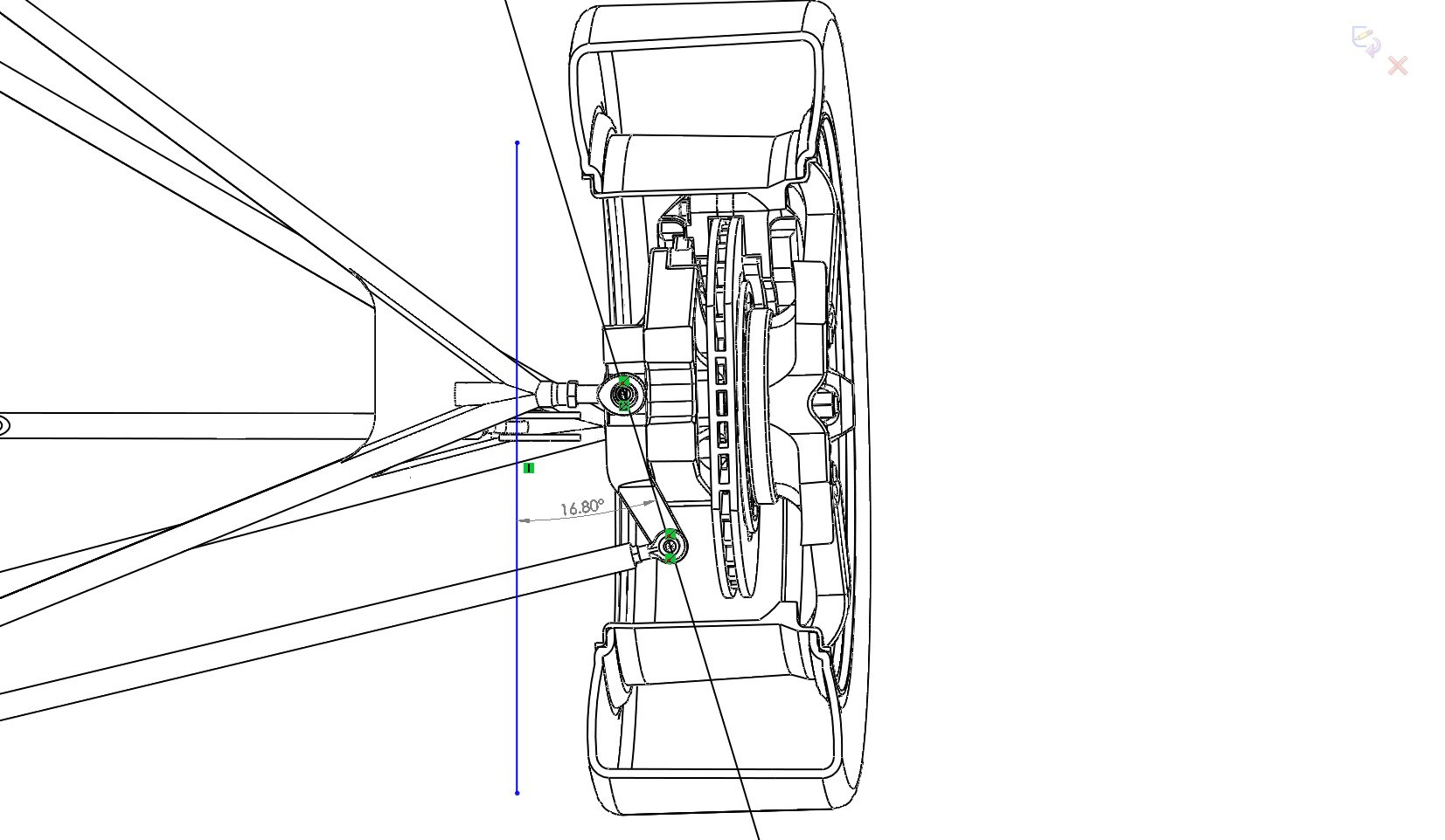
The sister terms to Kingpin Inclination and Scrub Radius are Castor Angle and Mechanical Trail. Castor Angle is the angle between the vertical and an imaginary line drawn between the outboard suspension mounts, this time from the side view. Mechanical trail is the distance measured from where the Castor line crosses the ground plane to where the vertical line passing through the center of the wheel crosses the ground plane. In reality the center of the tire contact patch sits slightly past center opposite the direction you are traveling so the real trail is a bit longer then the calculated trail. This difference is know as Pneumatic Trail. The larger the trail the more resistant the wheel will be to steering input and the more it will want to self align to its point of minimum energy (straight forward). Lighter vehicle like trikes tend to turn more easily so having a decent amount of trail to help it go straight is a good thing. The heavier the vehicle the more it wants to continue on in a straight line and so the less trail is needed, and even negative trail (negative castor) is sometimes used to make the car more responsive. This is like making an aircraft that is so unstable a computer is needed to make it fly straight, the instability makes it extremely responsive.
The Castor line does not need to pass through the center of the wheel, which allows the angle and the trail to become independent of each other. However just by thinking about this for a minute we realize that moving the Castor line from center will cause a scrubbing effect when turning because the wheel center rotates around the Castor line. This is not something that is ever done to my knowledge.
Another important term is Toe Angle which is the static position of the wheels (front or rear) at ride height and with no steering input. This can be used for all sort of good and bad things. Toe IN is when your aim the wheels at each other in the forward direction, and Toe OUT is when you aim the fronts of the wheels away from each other. This is usually measured as a length and not an angle, although the angle can be calculated very easily from the length if the tire/rim radius is known. More pictures and info on this later.
________________________________
jim99
Exalted Member
Posts: 116
Post by jim99 on Mar 7, 2012 at 8:16pm
Hi Andrew,
Great information that you are sharing with everyone. Hopefully everyone is reading this thread.
The positive of having Scrub Radius is it helps to provide steering feel and feedback to the driver.
If you have zero scrub radius (called centerpoint steering) the driver will complain that the car is "darty", the steering reacts too quickly and that there is very little steering effort and feedback to the driver.
The negitive effect of scrub radius is that it will cause the tires to build heat and increase tire wear.
So that means we need to find a happy medium.
The only feedback I can give is that I built a trike with about 1/4" of scrub radius. Very unpleasant to drive or ride in.
This winter I have rebuilt the front end and now have about 1 1/2" of scrub radius. Once the snow is gone and I have driven the trike with the new front end I will update as to if I feel I have too much or too little scrub radius.
Jim
___________________________________________________
Post by captainamerica on Mar 10, 2012 at 3:29am
Thanks for the input, I really haven't driven any vehicles with adjustable scrub radius. So I have no idea what it feels like. Good to know.
___________________________________________________
Post by captainamerica on Mar 10, 2012 at 4:23am
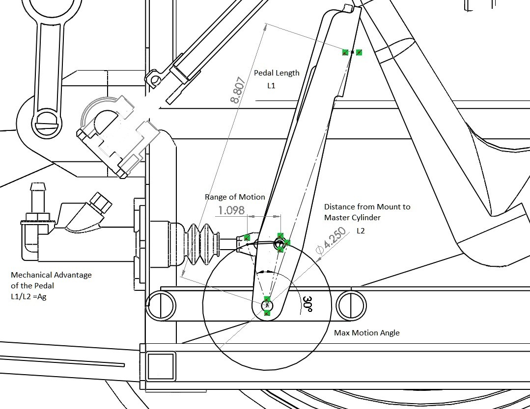
Quick Detour to the Brake World
Brake Pedal to Caliper Calculations
I use Wilwood brakes because they are cheap, and the company provides extensive information about all their products. This is a break down of the front brake force calculation I used to size the master cylinders and see if my pedal size was right. The brake pad material determines the coefficient of friction between the pad and the rotor. Wilwood street pad material comes in three forms BP-10/20/30. I chose to start with BP-10 because its cheap. I used the point of 400F for the coefficient determination because its where BP-10 and BP-20 Cross. This was arbitrary, once I have pad temperatures from testing then I will reapply the calculation. The spartan trike uses the following calipers and master cylinders.
Wilwood Forged Dynalite Info
wilwood.com/Calipers/CaliperList.aspx?subname=Forged%20Dynalite
Wilwood 7112 Brake Pad Info
wilwood.com/BrakePads/BrakePadsApp.aspx?compound=BP-10
Vehicle Calculations
Vehicle Weight = 1100lbs (estimated currently)
CG Height = ~16in
Wheelbase = 95in
Tire Info = 205/40R17
Tire Width = 205mm/25.4(mm/in) = 8in
Tire Wall Height From Rim = 8in*(40%) = 3.2in
Total Radius = (17/2)in+3.2in = 11.7in
Wheel Radius Under Load = 11.7in - .4in (estimated) = 11.3in
Tire Coefficient of Friction = CfT = 0.8 (average tire)
Front/Rear Weight Distribution = 55/45 (estimated)
Load on Front Wheels (2) = 1100 * (55%) = 605lbs
Static Load on Rear Wheel (1) = 1100 - 605 = 495lbs
Static Load on Each Front Tire = 605lbs/2 = 302lbs
Acceleration Force
Max Acceleration = ~0.5G
Load Transfer Under Acceleration at 0.5G = (0.50G*1100lbs*16in/95.5) = 92lbs\
Total Load on Rear Wheel = [(1100lbs*.45)+92lbs] = 587lbs
Max Traction Acceleration Torque = Traction Force * (CfT) * Wheel Radius Under Load = 587lbs*(0.8)*(11.375in/12in)ft = 469 lb-ft
This sections solution is questionable by me, use at your own risk.
Braking Force
Load Transfer Under Braking at 0.8G = (0.80G*1100lbs*16in/95.5) = 147lbs
Total Load on Each Front Wheel = [(1100lbs*.55)+147lbs]/2 = 376lbs
Max Traction Braking Torque = Traction Force * Wheel Radius Under Load = 376lbs * (11.375in/12in)ft = 330 lb-ft
Total Load on Rear Wheel = [(1100lbs*.45)-147lbs] = 322lbs
Max Traction Braking Torque = Traction Force * Wheel Radius Under Load = 322lbs * (11.375in/12in)ft = 305 lb-ft
Front Caliper Calculations
Number of Pistons = 4
Piston Bore Diameter = 1.375in
Total Piston Area = PI*Radius^2 = PI*(1.375in/2)^2 = 1.48in^2
Total Piston Area Per Rotor = 1.48in^2 * 4 (# of Pistons) = 5.940in^2
Coefficient of Friction (Cf) = 0.42 (BP-10 Pad@400F)
Rear Caliper Calculations
Number of Pistons = 2
Piston Bore Diameter = 1.25in
Total Piston Area = PI*Radius^2 = PI*(1.25in/2)^2 = 1.23in^2
Total Piston Area Per Rotor = 1.23in^2 * 2 (# of Pistons) = 2.46in^2
Coefficient of Friction (Cf) = 0.42 (BP-10 Pad@400F)
Pedal and Master Cylinder Calculations
Pedal Length (L1) = 11 in
Bias Bar Point (L2) = 4 in
Pedal Mechanical Advantage = L1/L2 = Ag = 2.75
Pedal Motion Ratio = L2/L1 = .363
Pedal mechanical advantage is how much more force I get at the master cylinder then the foot, and the motion ratio is the inverse or Ag and it determines how far the master cylinder will compress for any motion in the pedal. If I move the pedal contact point 1" with my foot I will move the master Cylinder ~.363".
Master Cylinder Size Determination
The larger the bore the harder it will be to push the pedal, some people like to have an extremely stiff pedal while others want to be able to feel the pedal move so they can better determine the required force to stop. I used 3/4" the front and 5/8" on the rear bore on. The smaller the master cylinder the more responsive the brake will be as line pressure will increase much faster.
Master Cylinder Bore Diameters (Shown for Comparison)
D= 5/8 = .625in A=.307in^2
D= 7/10 = .7in A= .384in^2
D= 3/4 = .75in A= .442in^2
D= 7/8 = .875in A= .601in^2
Volume of Fluid Used at Front Calipers (2) = Distance Traveled * Total Piston Area = .01in * (5.940*2)in^2 = .1188in^3
Distance Master Cylinder Moves = .1188in^3/0.601in^2 = 0.198in
Foot Motion Required to Move Cylinder that Far = Distance / Pedal Motion Ratio = .198in/.24 = .83in
Volume of Fluid Used at Rear Caliper (1) = Distance Traveled * Total Piston Area = .01in * (2.46)in^2 = .0246in^3
Distance Master Cylinder Moves = .0246in^3/0.307in^2 = 0.08in
Foot Motion Required to Move Cylinder that Far = Distance / Pedal Motion Ratio = .08in/.24 = .83in
You can work out this set of equations until you find a distance of pedal motion that works for you. Smaller diameter master cylinders will give larger pedal motion. Changing the pedal motion ratio can also be toyed with the allow you to hit any pedal distance you want.
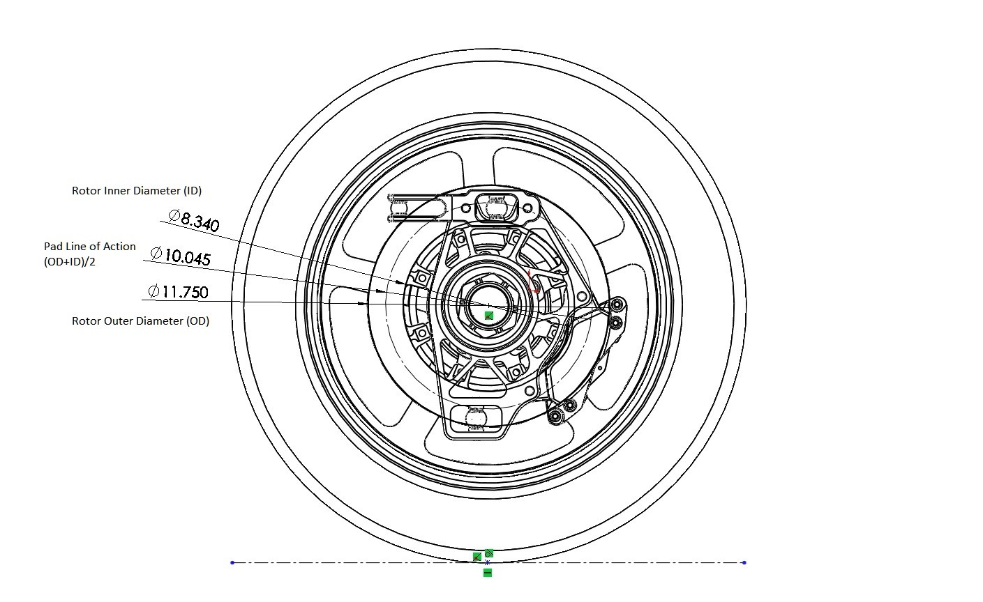
Brake Torque Calculation
Applied Foot Force = FA = 100lb (Assumed, I have yet to measure this)
Force Applied to Master Cylinder = FA*Ag = 80*2.75 = 220lb
Bias To Front Wheels = 50/50 (Bias Bar Centered)
Line Pressure for 3/4" Master Cylinder = 220lb*(50/50)/0.442in^2 = 497 psi
Line Pressure * Piston Area per Rotor = Force Applied to Rotor = 497psi * 5.940in^2 = 2956lbf
Force Applied * Cf of Pad = Brake Force = 2956lbf * .42 = 1241lbf
Front Brake Force * Rotor Average Radius = Brake Torque = 1241lbf * (10.375in/12in)ft = 1073 lb-ft
Line Pressure for 5/8" Master Cylinder = 220lb*(50/50)/0.307in^2 = 716 psi
Line Pressure * Piston Area per Rotor = Force Applied to Rotor = 716psi * 2.46in^2 = 1762lbf
Force Applied * Cf of Pad = Brake Force = 1762lbf * .42 = 740lbf
Front Brake Force * Rotor Average Radius = Brake Torque = 740lbf * (3.70in/12)ft = 228 lb-ft
So from this calculation I can see I need to do a little work, I have approximately one and a half times as much brake force as the wheel can theoretically handle (228/226 = ~1). This is close enough for me to test out and see if it works in the current configuration.
_________________________________
Oct 1, 2014 at 9:54pm
Post by captainamerica on Oct 1, 2014 at 9:54pm
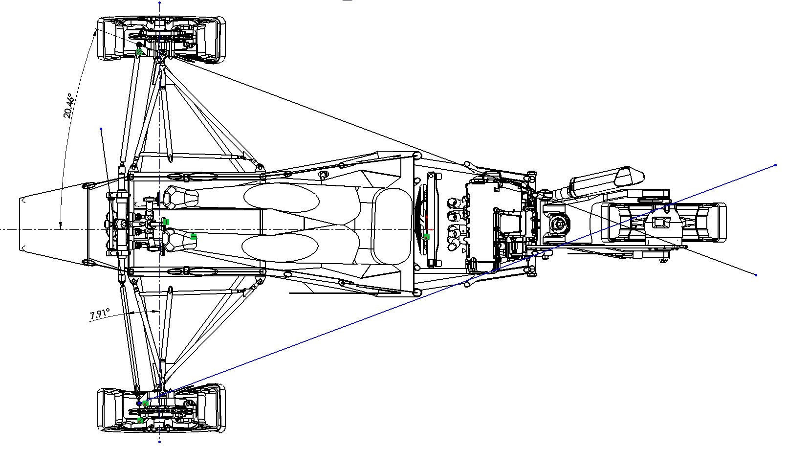
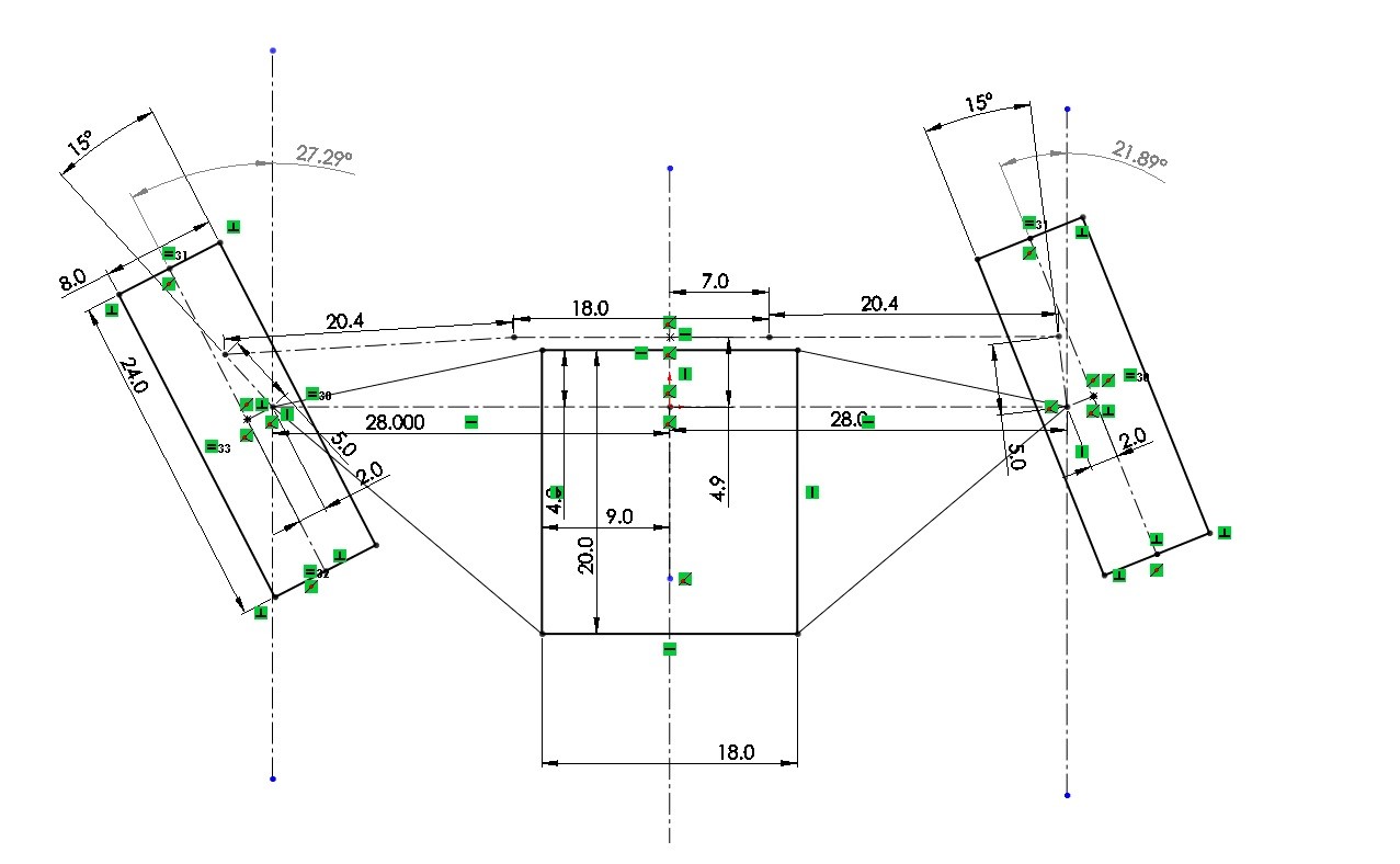
Next up is Ackermann Angle, this is the angle between the center line of the car (from the top view) and the imaginary line drawn from the steering mount point to the closest A-arm mount point. The closest mount point depends on where the steering point is located on the upright. In the picture it is in the top front position. The steering rack plays an important part in how well the ackermann setup will work, in the standard case in which the rack is in front of the wheels (as shown), moving the rack away from a position that makes the steering tie rods perpendicular to the direction of travel (in the top view) will decrease how much effect ackermann steering has. In the case shown the steering rack is moved forward to fit the driver and so the ackermann angle is actually more then "full ackermann" to compensate.
Ackermann steering is usually used to make the inside wheel rotate more then the outside wheel in a turn, the radius that each wheel takes should be matched to the turns that the vehicle will be making, this is easier to calculate for race cars on fixed tracks with known radius curves. Full Ackermann is a term used to describe when the left and right Ackermann lines meet directly over the rear axle center line. Ackermann angle is a bit subjective as far as what works. Racecars sometimes use reverse ackermann to create more favorable slip angles with their tires.
Something to note, we can see that there is empty space in from of the steering bolt point which could allow us to move that point forwards on the upright to help make the steering tie rod at less of an angle but this would in turn reduce the amount of total steer angle allowed because of the increased distance from the kingpin axis. This is all about compromise and knowing what we need, how hard do the wheels need to turn, I suggest going out to your daily driver, turning the wheels all the way to a left or right lock and measuring the angle they make, I did this with two 2x4s and a protractor. If you measure both wheels you can get an idea of the amount of ackermann used by the major manufactures.
In the case of a mid height steering mount you would want to calculate how far you are from the 3-D line created by the castor and kingpin lines.
Below is a picture of a theoretical car making a turn on a 10 foot radius, we would only see this in parking lots and u-turns maybe but I did it this way so you could see all the numbers clearly. As you can see the center of the turn is shown as the point the rear axle passes through, this is good enough for this example. Perpendicular lines are then drawn to the center of the chassis (11 degrees) which is that actual direction the car is headed and then one each to the front wheels showing the difference in required steering angles for a "perfect" turn.
NOTE: The difference in angle between the direction the chassis is traveling versus the direction the wheel is aimed is the slip angle of the wheel, this is over simplified here.
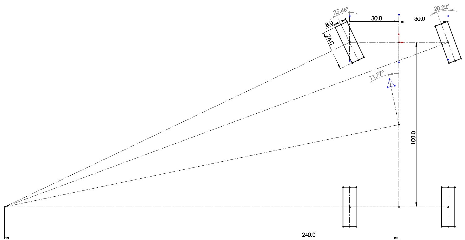
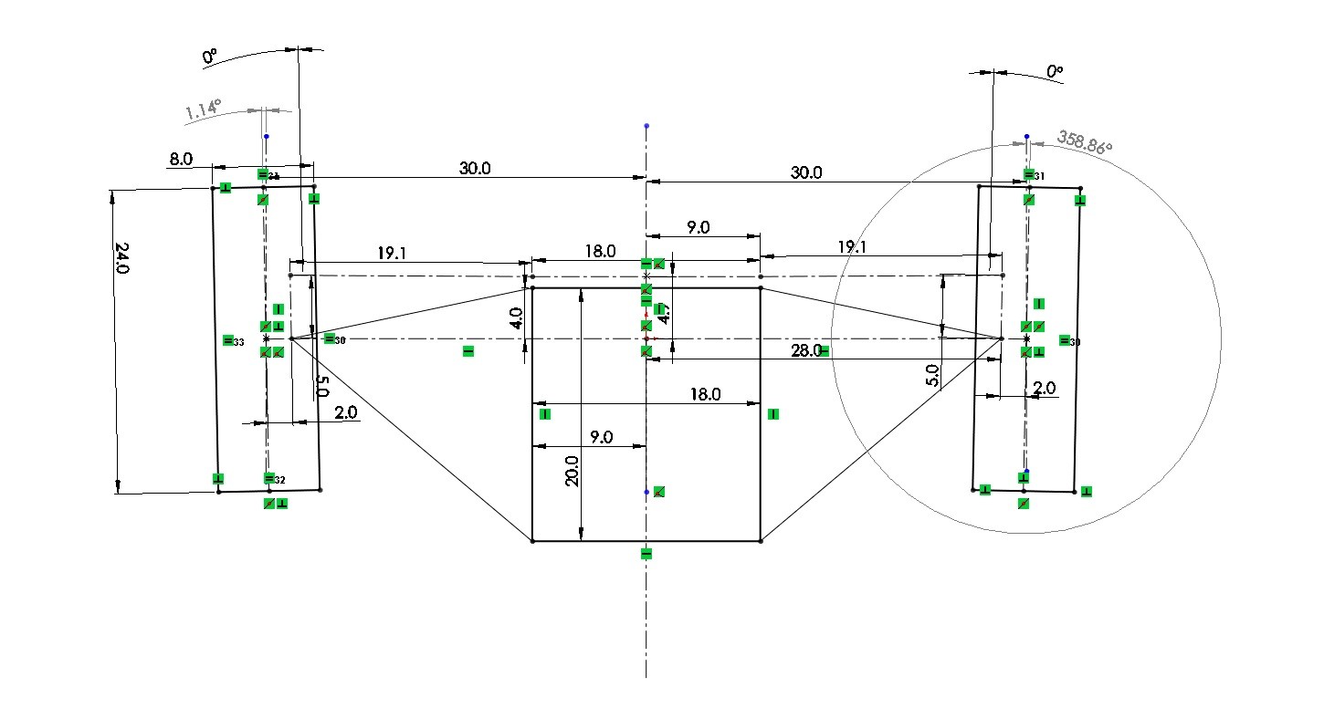
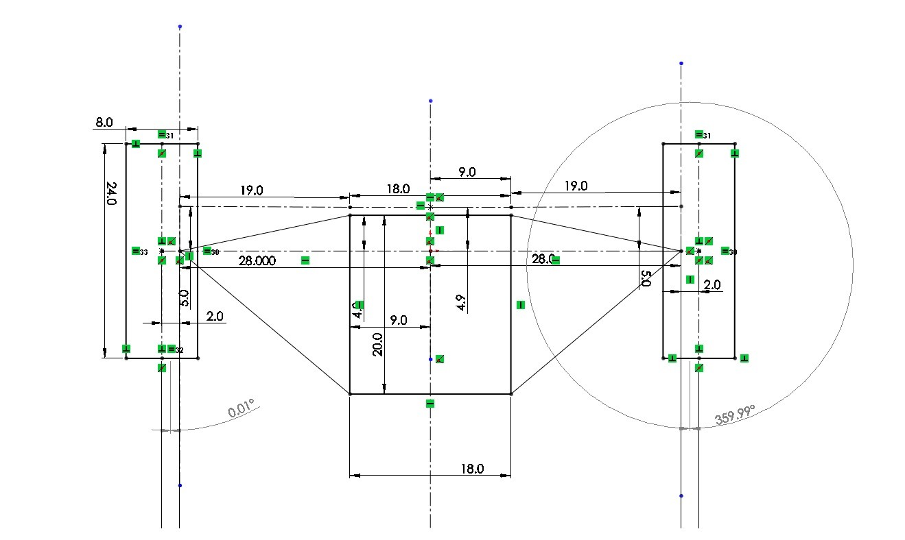
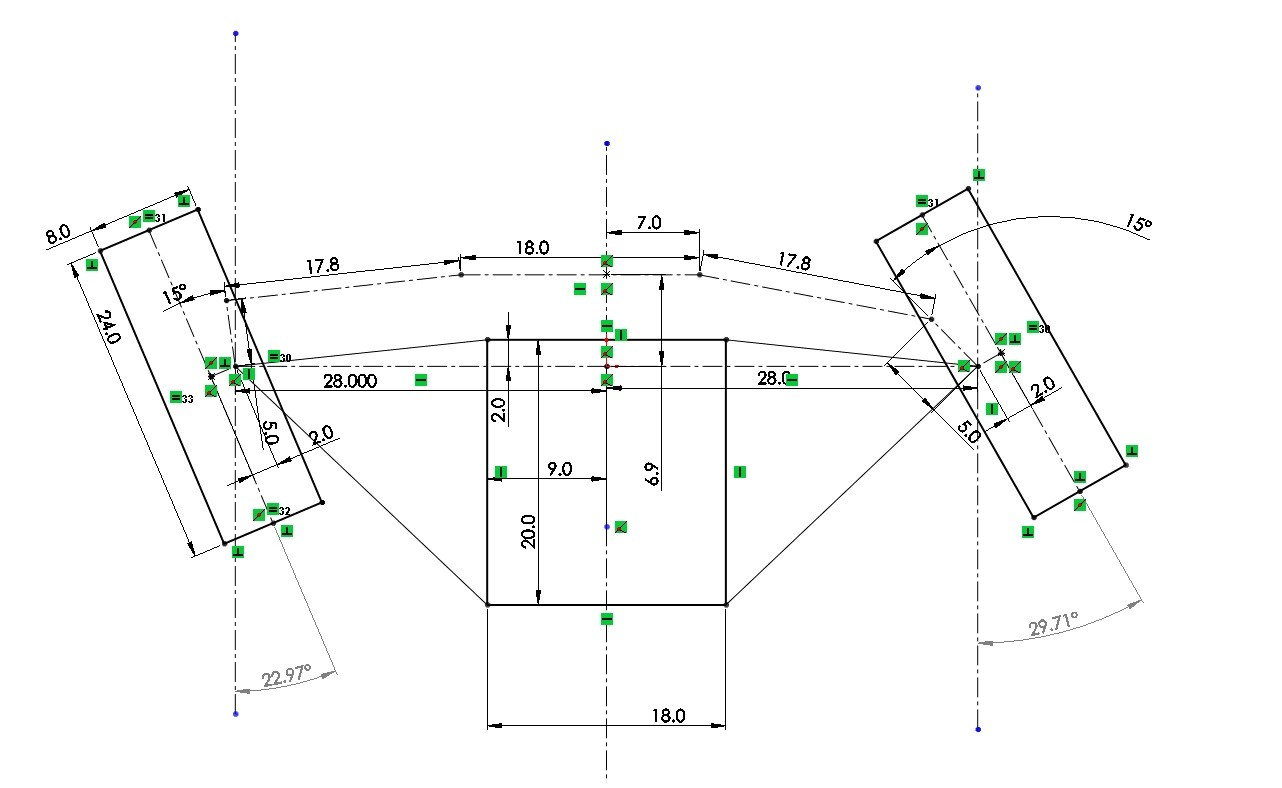
0 Degree Ackermann in static and steering. So this example is shown to show you why ackermann is used. We can see that the front suspension is shown in plan view, for simplicity I did not take into account kingpin or caster in this model. The scrub radius is 2 inched, the top and bottom A-arm attachments are directly over one another and the steering attachment is 5" in front. After I did the setup I added in the 18" wide steering rack and made sure it was in a position so that the steering tie rods were very close to horizontal. We can see that when we turn both wheels turn almost the same amount, we lose a little due to the scrub radius moving one wheel back and the other forward but its still pretty good. However we know from the previous picture that one or both of the wheels will be dragging on the pavement because they are not aimed along the line of travel for the turn we are attempting.
 .
.
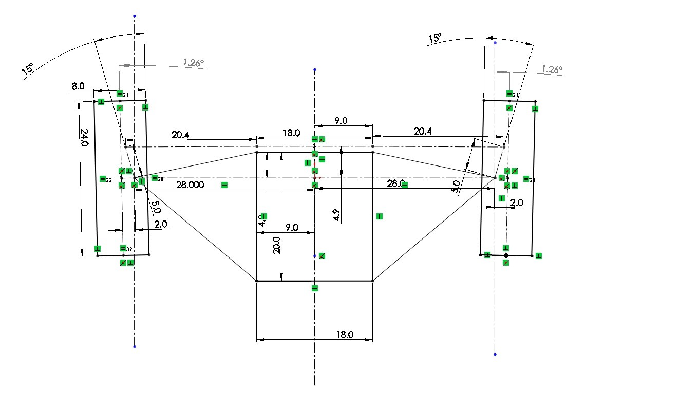
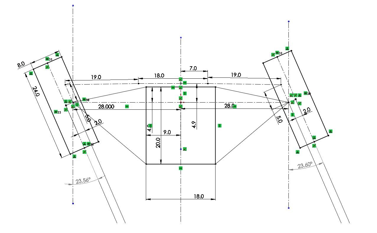
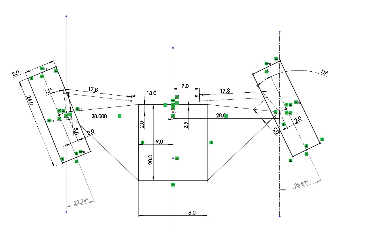
15 Degree Ackermann in static and steering. Now I have taken the same setup, added 15 degrees of ackermann to the setup and adjusted the steering tie rod length accordingly, this is crucial otherwise your wheels would not be straight when you went straight, this will not be repeated but it is done in all of the following examples. We can see that we are very near the hoped for ackermann angles using this 15 degree number. It is not shown here, but at 15 degrees and this wheelbase as shown in the first picture the ackermann is just slightly past full, so the lines intersect just in front of the rear axle center line. It is crucial when measuring your ackermann intersect that the toe angle be zero degrees as it directly adds to the ackermann in this calculation.
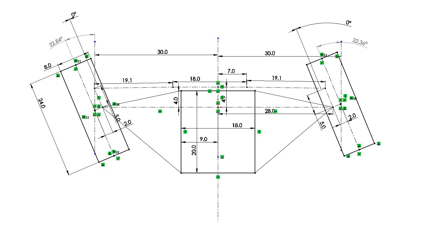
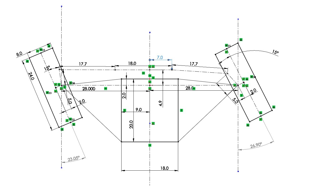
2" forward position of the steering rack static and in turn. So now the steering rack is moved forward 2". We can see that this has negatively affected our outcome, we need to add more angle to compensate for this, This is very similar to the setup on the Spartan, which works well but I had to use a larger angle which has turned out really well. This angle has limits though, most noteably the rim and the brake rotor, these box you in when you put your steering point at the top or bottom of your upright. However because of the castor angle, as in my setup, the top front and bottom rear become the best places as the upright leans away from these locations giving us more room to play. NOTE: This setup occurs much more often because performance vehicles usually want to minimize wheel base to assist with minimum turn radius and the rear wheels are kept inline with the transmission outputs to minimize power losses from the drive train. The last generation of indy cars (2000s) used approx. 3" of forward position of the rack.
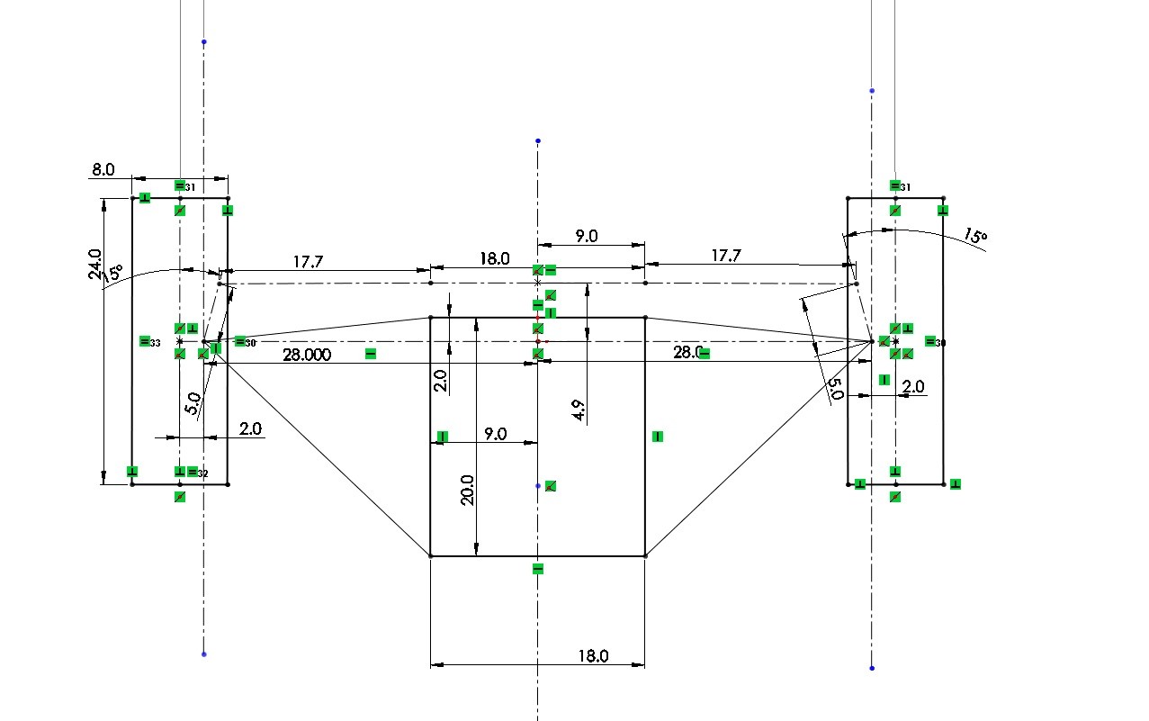
2" backward position of the steering rack static and in turn. In the case that your car is to small and you want a longer wheel base, this can occur, but it is not preferable to straight in my opinion and is harder to package. It can be seen to have a positive effect on your ackermann allowing you to run less angle, in the same way that moving the rack forward can have a negative effect.

I will add the same analysis for a rear mounted rack in the near future.
NOTE: An interested case that occurred on the Spartan when I first got it rolling. I was using the water jet cut steering attachments which have zero ackermann built in, my rack sits about 3 inches forward form horizontal and this caused a negative ackermann angle when turning. The inner wheel would barely turn and the outer wheel would turn drastically making moving the thing around the shop a total pain.
_________________________________________________
Post by captainamerica on Oct 4, 2014 at 12:41am
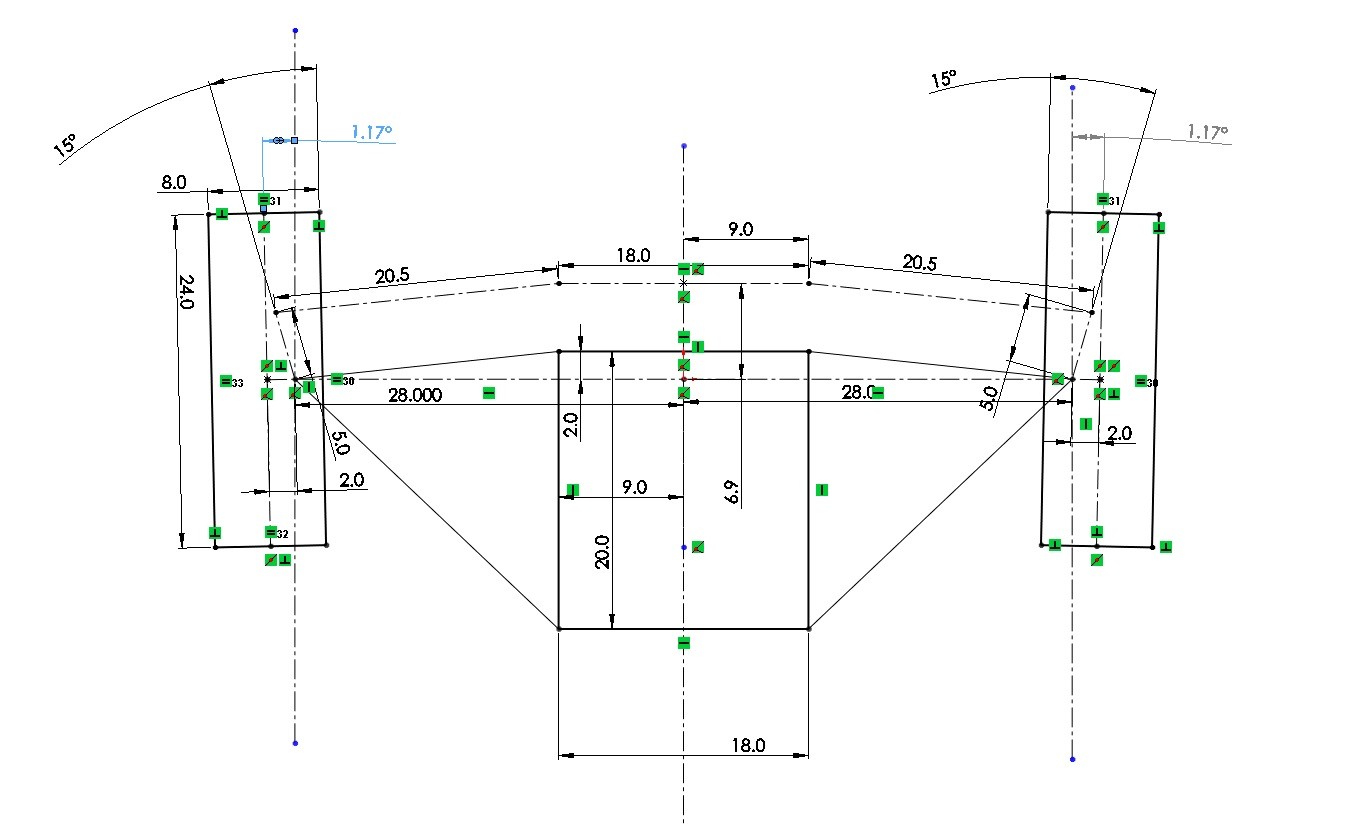
This is the follow up post to the ackermann steering design post above. Here we are looking at a rear mounted steering rack, the vehicle is now going to the opposite direction for simplicity on my end.
0 Degree Ackermann. This is very similar to the front mounted setup, almost exactly the same steering angle for both tires in a turn just as we would expect.
15 Degree Ackermann. This shows an immediate advancement in the right direction. The real down side of having rear mounted steering is that you almost always have to put it on the bottom of the chassis which is alright but then the steering column has to go between your legs, which can be less then pleasant and your column as to make a 90 degree turn usually.
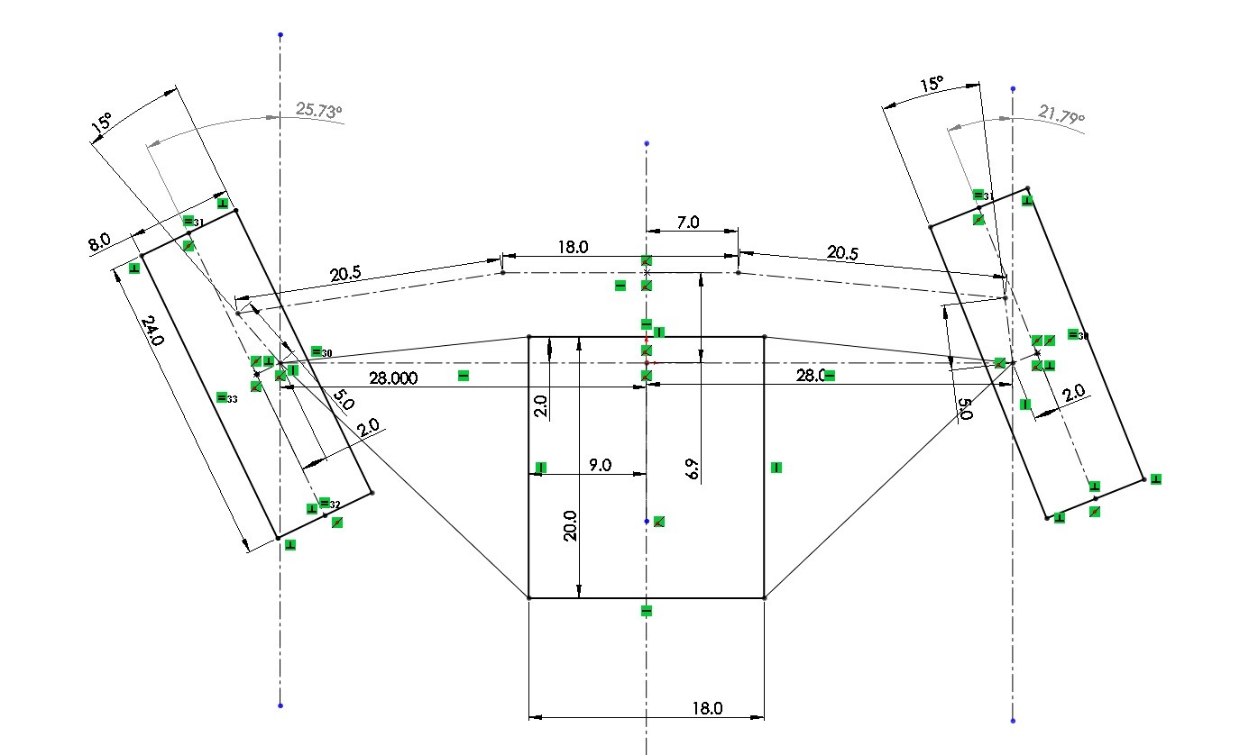
15 Degree Ackermann. Here I have moved the steering rack backwards in the chassis relative to the steering mount to the uprights. This helps the ackermann difference more then the following change and is actually better then the standard.
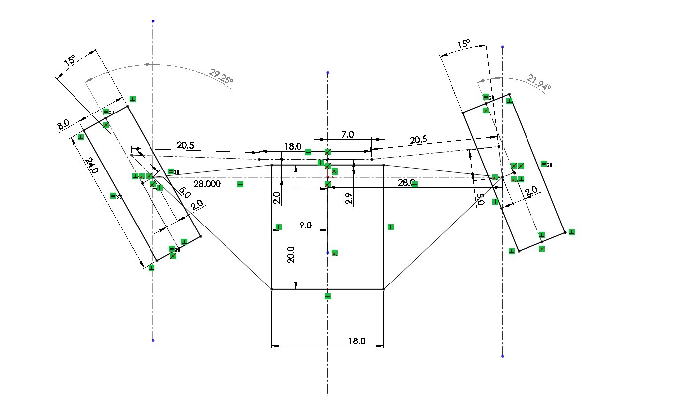
15 Degree Ackermann. Here I have moved the steering rack forwards in the chassis relative to the steering mount on the uprights. The outcome is not as good as the straight horizontal tie rods which was expected. This is the reverse of the outcome of the front mounted rack just as would be expected since everything is basically mirrored across the front axle plane. The further forward you but the steering wheel the tighter the turn the column will make so it may be a requirement to move the rack to a position that actually works and hopefully allows the column not to bother your legs to much. It is also very simple to move the wheels (changing the wheel base) and alter your setup. If you are using some sort of stock car suspension then the A-arms are probably already fixed and you are now just needing to come up with a compromise for the steering system that works for you as the driver.
________________________
skifffz1to3
Full Member
Posts: 101
Post by skifffz1to3 on Oct 4, 2014 at 9:06am
This is awesome. You continue to pour 10 gallons of information into a 5 gallon can! However, in my own case, I've got my can sitting in a 500 gal washtub (internet/this forum thread) so I can save, and re-pour as needed to absorb it all. Keep pouring!
________________________________
captainamerica
Exalted Member
Post by captainamerica on Feb 14, 2015 at 10:38pm
I asked myself the same thing.
_________________________
Liteway
Exalted Member
Post by Liteway on Feb 7, 2016 at 10:49am
This is a great post that must have taken considerable time to compose. While I find it hard to absorb it all, It's a help to have this post for reference for particular questions right here on the site.
________________________
captainamerica
Exalted Member
Post by captainamerica on Mar 27, 2016 at 1:56pm
Finally getting around to adding to this.
Roll Center is up next. The roll center of an independent suspension design is found by following the lines of the A-arms from the front view until they intersect and then draw a line from that intersection (also known as the instantaneous center) back through the center of the contact patch, when this is done to both sides of the suspension, the line through the wheel contact patches will cross (on the center of the vehicle in a road course setup). For an oval track this wont be true. Also note that parallel suspension points will never intersect and this analysis can't be done on them, however unequal length suspension geometry can only be parallel at one point if at all.
The suspension shown below just hit a bump, pushing the front wheels two inches up, I just did this so that it was easier to separate the line through the contact patches, normally I would do this by varying the ride height and leaving the wheels fixed to the ground.

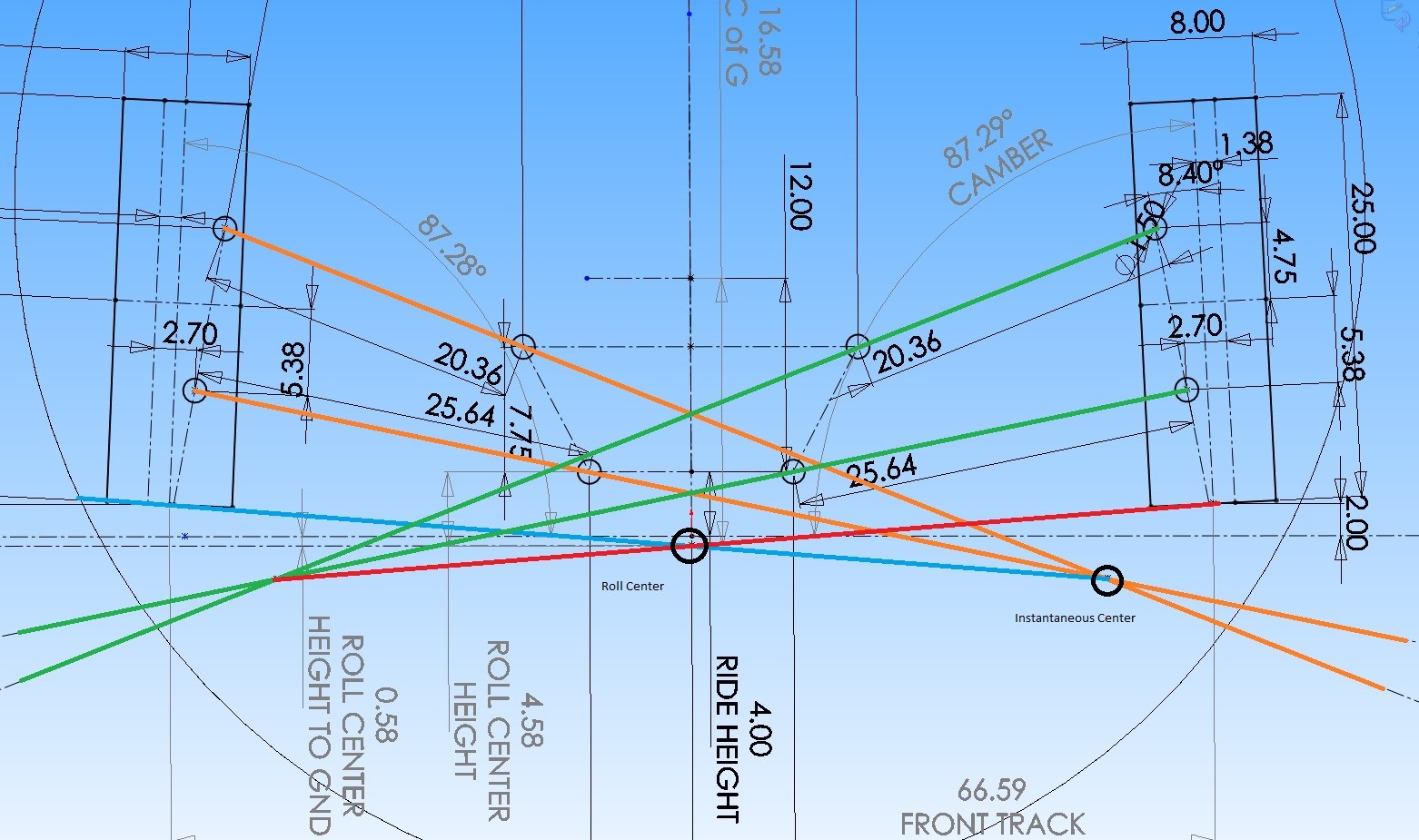
In my experiments with this setup sketch I was surprised to find that the roll center does not move with relation to the chassis as the wheels move through their motion. Whatever you set as the static roll center height it will stay generally around that point, mine moved 1/10th of an inch from my static height of -0.50 below ground over the +/-3" range of motion. Just to reiterate, this is talking about the measured distance from the chassis to the roll center, not the distance from the fixed ground plane, both are shown in the drawing.
If we find both the front and rear suspension roll centers, then a Roll Axis can be drawn through the two roll centers longitudinally for the chassis and it will show you the axis that the car will roll around. This is not that simple since as the car rolls the roll center moves. In a three wheeler the rear end is simple, the roll center is at the center of the contact patch in the rear on the ground plane. Generally speaking from what I have seen and read a lower roll center in the front is desirable giving the roll axis a slight angle down towards the front. What this means for us reverse trike folks is having a roll center below ground at static ride height would be a good starting place.
The line between the CofG and the roll center is a moment arm which determines how much advantage the vehicle has over the resistance of the suspension. Just imagine a pry bar arcing over to pull a nail out, the further your hand is from the nail the easier it is to pull. The more mass you have the more the car will want to roll and the further that mass is from roll center the easier is will get the car to roll. I do not know the results of putting the roll center on top of the CofG or extremely far under ground, max and min roll arm lengths, but I would guess that any gain that came from that design would cause an even bigger problem elsewhere.
SIDE NOTE: A friend of mine awhile back designed a suspension system where the upper and lower A-arms crossed one another, the upper chassis mounts connected to the lower ball joint etc, this was his plan to get large camber gains from small chassis rolls and then limit chassis roll quite a bit. Not sure how this would ride but it looked pretty interesting on paper.
_______________________________
captainamerica
Post by captainamerica on Mar 30, 2016 at 7:13am
The way it rides is a very non-specific idea that will vary from person to person, but in general I would have to say no you wouldn't want to move the roll center up high as the roll axis would be severely angled upwards toward the front and the driver would have a rather strange feeling for how the car is turning in. If someone wants to try it out I would be more then willing to listen to how it turns out. That being said there is a lot to be said for the amount of camber gain through bump and roll based on the location of the instantaneous center, I am going to do some looking into about exactly how this affects things but the idea is that the further the center is from the wheel in question the less camber gain or change you will see for a motion of the wheel.
_______________________________
endeavor
Junior Member
Post by endeavor on Apr 9, 2016 at 9:12am
It's been awhile since I toured this board. This is an interesting and very intuitive posting. You have done a great job Mr CA in explaining all the things I have learned the hard way :-)
To date I hand built 4 prototype units and rebuilt most of them at least 3 times mostly due to things I learned over the years regarding KPA, caster settings, scrub, turning radius and camber settings. It's such a contrast reading the tech data here regarding all these things then going onto the Spyder site and reading all the postings on Laser alignment to set toe and the perceived great handling improvements. (again a giggle)
One thing I have come across here in the last year has been the importance of tie rod height which I would like to share.
Like the CanAm my design does not use idler arms rather a single tie rod on each side connected to a steering shaft directly. While this is simple and works well one problem is determining where to set the steering shaft / rod connections as far as height. Now if the distance from the lower ball joint to the tie rod location is say 5 inches then the distance at the steering head will have to be slightly less than 5" or in my case I set this at 1/2" less.
Here is the reasoning. during body roll if the steering heat height is higher than the wheel location height then the unit will tend to try to counter steer and attempt self corrections resulting in the unig darting back and forth it will also drift badly in the corners. having the center attachment lower will offer a more gradual and natural positive drift. Feedback is more inline with what is expected and all motions are softened.
I also now build all my own A-arms and found as the scrub is reduced I have to add more caster. Also the caster and camber angles vary with vehicle size and weight.
Another thing with is overlooked by even the "Big Boys" is aerodynamic profile. The large fiberglass enclosures some of the new entries are using are very detrimental to handling along with the larger 17 and 18 inch low and wide profile tires. In essence the center of pressure is moved ahead of the center of balance causing poor handling at high speeds and in windy conditions. It is best to have the nose small along with the tires to minimise the pressure area.
I actually met briefly with an aerospace scientist who filled me in on all this.
Another thing I do which goes completely against the grain and logic of suspension is to use very heavy wheel assemblies. This was not my original desire but as it turned out the easiest and cheapest route to go is to simply use automotive components. Normally you want upspring weight low so the wheels stay on the ground however the unforeseen benefit of the heavy wheels is they add dramatically to the stability in corners as the heavily weighted wheels act as ballast and effectively lower the roll center as described above. This may not be the best on a 4 wheel unit but a 3 wheeler tends to also "woddle" which helps control the tires keeping them planted. I find my trikes will slide in a corner rather than tip so the effect is dramatic. Tire pressure on my setup is 16psi front and 26-30 rear so the tires actually absorb most of the road irregularities.
While I have learned much over the past 7 years and 144,000 miles i just know a fraction and keep learning each day. Thanks for all the great information.
Endeavor Trikes went into production July 2014 and so far 13 units on the road all hand built all customs and it's all good.
________________________________
noahkatz
Junior Member
Joker,
Why do you think ride quality is related to roll center height?
But to answer your question, yes, if the roll center is at the same height as the CG, there would be no body roll in corners, other than from changes in rolling radius of the tires.
The problem with that, at least for A-arm suspension, is that vertical motion of the tires causes them to scrub laterally.
You can see this by visualizing the motion of a virtual suspension arm which you create by drawing a line from the roll center to the center of the contact patch.
____________________________
endeavor
Junior Member
Post by endeavor on May 11, 2016 at 8:50am
In reading all the info here and meganracing I have made some changes to my current design. I was running my A-arms perfectly parallel but have lowered the top A-arm hinge 1.5 inches. I am using one piece tie rods with no idlers so the arc produced by the A-arms and tie rods didn't coincide during movement. Now they seem to. The first thing I noticed during bench test is now the toe adjustments remain consistent during suspension compression and extension so I no longer need to compensate for toe drift.
I have not road tested as I am still assembling but will share any conclusions when the time arrives. I am glad I came across this thread, still more to learn.
__________________________
Page 2
noahkatz
Junior Member
Post by noahkatz on May 14, 2016 at 1:50pm
Right, I still don't understand what ride quality has to do with roll center.
________________________________
captainamerica
Exalted Member
Post by captainamerica on May 14, 2016 at 8:41pm
Alright so I read Joker's question awhile back and didn't really have a good grasp on it, not sure if I do now but it seems to have generated some controversy. My comment would be that while you could make the roll "zero" by putting the roll center on top of the CG, you could also just reduce roll by using an anti-roll bar, want no roll, use a really stiff one. The bar at the front of the Spartan is way to strong but I can tell you that there is almost no roll in that vehicle. I really don't see the benefit to trying to design out the roll of the vehicle completely by moving the roll center, your camber curves would go to Poop I expect among other things. All of that said, ride quality is quite a subjective idea, someone might drive an indy car down a normal road and think that its way to stiff any time it hits a pot hole or bump, yet that same car on a speedway might handle like a dream yet they are the same car. So handling is more important relative to the roads you will be driving, I realize that roll in a trike causes loss of rear wheel contact patch if your using a car tire, but tires especially at lower pressures can handle "camber" and still keep a reasonable contact patch. So I think if you just limit your roll using an anti-roll bar you will find what you are looking for without compromising your suspension design all for one parameter.
_______________________
DaveJ98092
Administrator
Post by DaveJ98092 on May 14, 2016 at 10:51pm
A roll (SWAY) bar of the correct size will work like Andrew said. It makes suspension design a bit easier. The (slight) problem with roll bars is it also limits a independent suspensions independence some what, but do you really need true 100% independent suspension?
I had a Chevy 3500HD dually truck with a SOLID I beam front axle and Kingpins, not ball joints. It would corner with almost any non sports cars in corners. My son had a 85 Toyota SR5 4X4 pickup that had a solid differential axle up front. One day his his Autocross car broke at the track and he asked if he could take the pickup out and give it a run JUST to see. It was in the middle of the slow class of CARs as far as time.
____________________
endeavor
Junior Member
Post by endeavor on May 15, 2016 at 7:25am
You are correct in the assumption an anti-roll bar of sufficient heft would zero out the roll nicely. It would also limit the independance in the suspension. However there are substantial differences between a 4 wheel vehicle and these tadpole designs as far as suspension and cornering dynamics. On a 4 wheel vehicle you can tune your handling and ride characteristics both front and rear. You would be running anti-roll on both ends and 4 wheeler tends to run down the road fairly flat while the individual wheels move quite independently. On a trike things are slightly different as there is not sway stability on the rear as the rear wheel acts as a hinge allowing movement without resistance. All the tuning, anti sway roll center etc is totally up to the front end geometry. Trikes also do something which I call waddle. where the trike body tends to rotate as the wheels encounter bumps as there is not any resistance in the rear to offset this action. Even with soft roll bar and soft suspension this waddle will occur. One does acclimate to this however quite quickly but a newbie tends to feel the trike is moving laterally or dodging sideways when in fact it is just the waddle that offers the illusion of lateral movement. So in general I believe a stiff anti-sway is a good idea as it solves some problems and only slightly exaggerates others.
I am open to other opinions I have done 180's on ideas many times.
_______________________
Liteway
Exalted Member
Post by Liteway on May 15, 2016 at 9:36am
You make some good points I have not seen expressed here before, pointing out there are trade-offs with a thick anti-roll bar, that simply making it super thick may not give the best overall result, there are always compromises to be made.
I would point out the "waddle" will be less apparent the lower the driver is located in the chassis, so its more of a problem with a sit astride trike.
4 wheel road testers sometimes refer to it as "head toss" which tends to be more apparent in high sitting suvs and pickup trucks, particularly if they are stiffly sprung.
__________________________
endeavor
Junior Member
Post by endeavor on May 15, 2016 at 9:50am
Yes I tend to forget most of the builds here are low slung and mine tend to focus more on the higher riding position. Good point. Yet the theory is the same just the perception differs.
One other aspect I have run accross which may or maynot be of interest. Because I don't run idlers on the tie rods the rods are a one piece unit. obviously this poses a small problem as the tie rod arc and A-arm arcs do not coincide. During body roll if the center mount on the steering shaft is higher than the balljoint to tie rod mount on the wheel the trike will tend to overcompensate for lean and drift by toeing in so you end up with an oscillation due to this aspect and the rider also trying to overcompensate. I found that in lowing the center mount position I can effectively slow down this oscillation to a controllable almost unnoticeable amount. For instance my tie rod to ball joint measure is 5" and my steering mount is 1" less so when there is roll the wheels actually toe out just a degree or so softening the drift to a very gradual amount. Raising the mount would cause the old Burt Munro 190mph head shake.
The theory is much the same as cargo ships vs passenger cruise liners. A cargo ship rides low in the water so it is very stable and will resist tip over in heavy seas however the rocking motion will be fierce and quick. A cruise ship rides high so these oscillations are gradual and soft, the purpose is to lessen the likelihood for motion sickness.
________________________
endeavor
Post by endeavor on May 16, 2016 at 11:51pm
OK I finished the latest build tonight. The top A-arm hinge was dropped 1-1/2" in hopes of altering the roll center. While I am sure it worked (the math would support this) I am unable to honestly comment. If all I did was make this change then I could voice an honest opinion however I also changed the A-arm design, shock mounts and even the shock length and the swaybar. With all these changes I can't commit to a report. All I will say is things are good and didn't get worse. The bike handled great before and does now.
You can see the A-arm stance here along with the anti-sway setup - the sway bar was also changed with this build. Camber is set to zero, Caster 8 degrees positive and toe 1/4" positive. Tire pressure is 17psi.
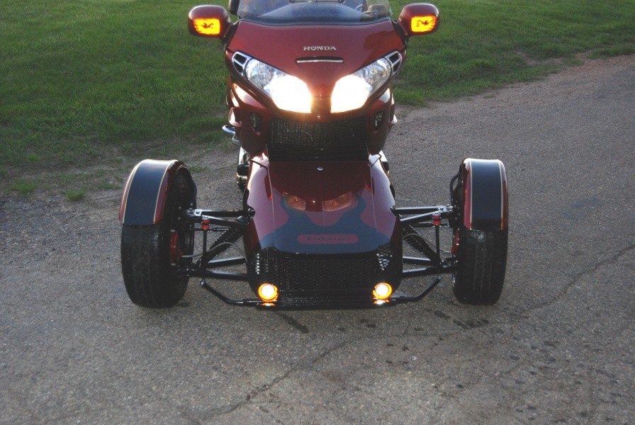
Sideview just for reference. Also a good view of the powercoated items
mtntech
Exalted Member
Post by mtntech on May 17, 2016 at 10:02am
Your tire pressure is interesting. I have been experimenting with lower pressures as well.
____________________________
endeavor
Junior Member
Post by endeavor on May 17, 2016 at 10:09am
BRP recommends 12.5 to 17psi on all the Spyders, of course most people (curbside engineers) are running 25 to 32psi as they can't seem to live with such low air pressure. The end result is a poor handling machine and tire mileage in the 8-9k range. The unit pictured has 22k on the tires and I fully expect 50k min.
A slightly higher pressure may be good for all out racing if you can control the bounce however in general tire patch is a result of air pressure vs applied weight.
At least this has been my findings regarding the matter.
One thing you may notice is the grill is pretty open so what air doesn't go around can pass through this reduces the forward pressure area and aids in high speed control and efficiency.
Last Edit: May 17, 2016 at 10:12am by endeavor
___________________________
Liteway
Exalted Member
Post by Liteway on May 17, 2016 at 6:19pm
I am struck by how much mass appears near, over the top or even behind the rear tire. Thats even before accounting for the mass of the driver, the high perched passenger and luggage seeming everywhere but where it might help balance. Track is not very wide. This will slide before it tips?
I will concede looks can be deceiving, but it looks unstable.
____________________________
endeavor
Junior Member
Post by endeavor on May 17, 2016 at 10:00pm
It is surprisingly stable and you are right looks are deceiving but the mass is all plastic the heavy materials are at axle height so even with a passenger it will slide before lifting a wheel. Keep in mind each front wheel also weights about 65lbs due to the heavy rotors and calipers (Chevy II) That really keeps the wheels planted.
I had some handling issues today and realize I was in a hurry and forgot to tighten the steering shaft lower bearing mounts so I had substantial play in the bars. Snugged her up tonight and it really handles well. Can't commit for sure but it appears there is slightly less lean so maybe the A-arm change did work OK.
__________________________
mtntech
Exalted Member
Post by mtntech on May 18, 2016 at 9:05am
What is the weight of your completed trikes?
_____________________________
endeavor
Junior Member
Post by endeavor on May 18, 2016 at 9:59am
The kit adds 140lbs to the base machine most of that is in the wheels which does sort of defy standard suspension ideals however it also greatly aids in stability as the wheels act as ballast weights. This was something unplanned and just happened due to product choice. This is also the reason my trikes are rated higher than CanAm in cornering tests as the CA will tip without VSS where mine stay planted. It has little affect on actual suspension dynamics mainly due to the low inflation rates. Tires being the primary suspension component.
Weight seems to be a concern mainly due to auto advertisers promising better fuel economy with less weight however this mostly applies to stop an d go as you well know the main fuel robber is not weight but air resistance. This is why autocycles like Elio can claim 80+ mpg. It is something I see here and on other RT forums is the desire to build in a streamlined body shell - it's a good plan.
The GL1800 which is the heaviest bike around comes in at +- 1100lbs complete after the build
Last Edit: May 18, 2016 at 10:01am by endeavor
_______________________
Liteway
Exalted Member
Quote
May 18, 2016 at 9:59am endeavor said:
The kit adds 140lbs to the base machine most of that is in the wheels which does sort of defy standard suspension ideals however it also greatly aids in stability as the wheels act as ballast weights. This was something unplanned and just happened due to product choice. This is also the reason my trikes are rated higher than CanAm in cornering tests as the CA will tip without VSS where mine stay planted. It has little affect on actual suspension dynamics mainly due to the low inflation rates. Tires being the primary suspension component.
Weight seems to be a concern mainly due to auto advertisers promising better fuel economy with less weight however this mostly applies to stop an d go as you well know the main fuel robber is not weight but air resistance. This is why autocycles like Elio can claim 80+ mpg. It is something I see here and on other RT forums is the desire to build in a streamlined body shell - it's a good plan.
The GL1800 which is the heaviest bike around comes in at +- 1100lbs complete after the build
end Quote
Your take on the effects of low tire inflation are certainly unconventional, and it's an interesting topic that I do not recall having been taken up elsewhere in the forum, despite it having a big influence on chassis behavior. Thanks for bringing it up for discussion.
I had mostly assumed, based on what I thought I knew, that the best inflation for dry tarmac was largely just a compromise with the ride harshness to be endured vs all other aspects of performance, that the flexible sidewalls that resulted from low inflation gave a cushier ride at the expense of greater rolling resistance and tread stability which in turn resulted in soggy handling, rapid uneven tread wear and increased fuel consumption.
Based on that and the low tire loads imposed on my very lightweight trike I rather arbitrarily selected 27/32 psi as my normal inflation.
Not very scientific of me, but those inflation pressures left me little to complain about the trikes handling, though it does ride a bit harsh, and the rear is a little loose under heavy throttle in tighter corners. I put tire pressures out of my mind and concentrated on other suspension tuning methods.
So now I read your take, and I was finally inspired to do serious testing of juggling pressures while every thing else remains the same.
Thanks for a fun afternoon, as I repeatedly returned to my favorite series of local tight turns to check the effects of the incremental changes.
16/28 psi.
(as compared to my normal 27/32)
Handling slightly more sluggish, with slower turn-in and much higher effort required, particularly noticeable at parking lot speeds.
In really pushing it through the turns, more body roll was apparent with a tendency to run wide through the corner (understeer) and slip at lesser speeds. The ride did improve by not so much as I expected. I would attribute that the trikes very low unsprung weight which allows the wheels to follow the bumps without asking for so much compliance from the tires. The tire/ wheel assembly weighs 14 lbs as opposed to your typical aluminum wheeled compact which is about 3 times that. I also have aluminum hubs and calipers along with small discs.
32/38
Not much change from 27/32 with ride and front end behavior about the same but with a bit better responsiveness. The biggest difference came at the rear where it stays better planted coming out of the corners with noticeably less wheel spin.
As for wear at the front with 10K of aggressive driving, I Don't have enough to project their ultimate life, but they already show a bit of weather cracking after 10yrs so that will be the reason they will ultimately have to be replaced.
I am hoping the discovery that the back tire spins less in tight corners with higher pressures will extend its life a bit as it is wearing pretty fast.
___________________________
endeavor
Junior Member
Post by endeavor on May 22, 2016 at 3:37pm
I can only speak of my own discoveries related to my specific configuration so you are right to assume the best fit will be one you devise. Part of the difference may be in rim type as I am running 6.5 inch wide rims with a narrow 165x60x15 tire so they are overstretched. This offers more lateral control. I am currently running into some mishandling issues with bikes that have the narrow 3" wide rear rim as I have to run a 175x70 tire which is just the opposite. That configuration causes a lost of side to side movement so the trike tends to jiggle from side to side especially in windy condition. Unless I can find a stiff wall tire like a run flat in the correct size I may have to go to a MC tire on the rear on those bikes. Most of the large asian tour bikes run a 5.5 inch rim on the rear so a standard 205 tire works very well with minimal side drift.
What I found on front tires is anything over 20psi causes tire bounce and center wear so lower works for my setup pretty well.
___________________________
Liteway
Exalted Member
Post by Liteway on May 22, 2016 at 7:13pm
Right. The trikes built here are so different in specification, that it would be highly unlikely that any 2 would work best with the same pressures. Even then , the qualities the builder is looking for will be different. Just as for example, one might be wanting a good ride and interstate stability, while another wants responsiveness and grip.
Not sure what you mean by bouncing; the wheel following sharp bumps up and down or overshooting them with the tire actually leaving the surface? The former would define proper suspension action, the latter needs better shock control. Or maybe you are referring to oscillations occurring after the bump. Again an indicator of under damping.
What kind of tires wear the center first with 20lbs in them? Most are designed the run near twice that. As I said, I have a very light trike and run 27 in the front and 32 in the rear. Both are wearing evenly across the surface. I should think running with 20 would wear the edges more quickly, especially as that would allow the edge to roll under when cornering.
I suspect that BRP recommends such low pressures and has Kendra deliver tires specifically designed to run at low pressures in order to limit cornering grip and promote under steer to discourage riders from approaching tipping speeds as a backup for the electronic nannies. OK, just my opinion. No facts there.
Most testers complain of slow handling and quick intervention of the nannies when testing the Spyders and I cannot help but think the under inflated tires are a factor in that.
Photos removed 11/12/16 to save data limits.
This is after 10k of hard use. Sorry for the repetition to those who have looked at my build posts.
_______________________
noahkatz
Junior Member
Post by noahkatz on May 24, 2016 at 2:24pm
Quote
May 14, 2016 at 8:41pm captainamerica said:
I really don't see the benefit to trying to design out the roll of the vehicle completely by moving the roll center, your camber curves would go to Poop I expect among other things.
end Quote
The biggest conundrum is suspension design is the ride/handling compromise.
The crux of this is that the suspension compliance needed for good ride compromises handling, because the resulting roll in cornering causes camber changes, uses up suspension travel, and the dynamic instability of the sprung mass sloshing around.
The reason for this roll is low roll center.
So IF there were a suspension that had high roll center (at the CG) without issues like the camber change and lateral scrub that wishbones give, the ride/handling compromise would be eliminated.
I've come up with a couple but the geometry is klutzy - lots of links, some very long that make packaging difficult.
May 14, 2016 at 8:41pm captainamerica said:
Quote
All of that said, ride quality is quite a subjective idea, someone might drive an indy car down a normal road and think that its way to stiff any time it hits a pot hole or bump, yet that same car on a speedway might handle like a dream yet they are the same car.
end Quote
noahkatz
That just says that a car that handles really well rides poorly.
Ride quality is not really subjective, in the sense that it's been established that a suspension frequency of 1 - 1.5 Hz is considered comfortable by the vast majority of people, whereas sports cars are in the range of 2 - 2.5 Hz; note that double the frequency corresponds to 4X stiffer.
__________________________________
noahkatz
Junior Member
Post by noahkatz on May 24, 2016 at 2:29pm
DaveJ98092
May 14, 2016 at 10:51pm DaveJ98092 said:
Quote
I had a Chevy 3500HD dually truck with a SOLID I beam front axle and Kingpins, not ball joints. It would corner with almost any non sports cars in corners.
end Quote
noahkatz
The only reason for having suspension is to deal with bumps; on smooth roads suspension type hardly matters.
I bet the track was smooth and your story would change on a bumpy surface.
Liteway
May 22, 2016 at 7:13pm Liteway said:
Not sure what you mean by bouncing...
My guess is all that unsprung mass oscillating on the tire spring.
What kind of tires wear the center first with 20lbs in them? Most are designed the run near twice that.
Other things being equal, half the weight (trike vs. car) means half the inflation pressure for the same size contact patch.
__________________________
noahkatz
Yep;a large unsprung weight has to be controlled with stiffer shock valving and this only adds to the ride deterioration caused by the heavy unsprung mass's inability to accelerate upward rapidly in response to a bump which in turn moves sprung mass along with it . Result: you and the chassis become part of the suspension or tied more closely to it.
In response that a trike that only weighs half of what a car weighs (at a given corner) needs only half the tire pressure to maintain contact patch sounds ok in theory.
There are a lot of variables with respect to the tire's construction and tread profile.
In my case, it's hard to find data on a 165/70r10 as not many cars use or have used it.
But going to the BMC Mini Cooper forums, the consensus seems to be 26 or 27 lbs up front is good for the street with considerably more for competition.
I am only ball parking figures here, as trying to be precise would be delusional.
Mini with driver aboard weighs about 1650 with 60 percent up front or 495 on each front corner.
My trike with driver loads each front with 193 . So the best pressure for maintaining the same contact patch as the mini drivers have would be 193/495=.39
.39x26lbs = 10.4 lbs. Interesting.
End of page 2
endeavor
Junior Member
Post by endeavor on Jun 17, 2016 at 11:02am
To clarify my comment on "tire bounce" Tire inflation rate is simply the amount of pressure required to form a proper footprint. Most tires I use are rated for a max load of 1350 lbs and a recommended pressure max of 35 psi. Now decrease the load and you must decrease the pressure or the footprint will become to small and the tire will tend to bounce. Think of a basketball - inflated hard as a rock, it will absorb little energy rather transfer this back into movement and the ball will bounce back almost as highly as initiated. Lower the pressure and the ball collapses and absorbs so much energy that it hardly rebounds.
Also in suspension dynamics the primary suspension component is not springs rather the tire itself. Whatever the tire can not handle is transferred to the spring and it's action controlled by the shocks.
The #1 purpose of suspension is to simply keep the wheel on the ground. Too stiff a spring and the wheel will skip over bumps, too soft and the suspension will top out. Improperly inflated tires will place greater demands on this control and will transfer an excess of shock stress to the secondary suspension system.
And that's all I got to say about that.
_________________________
joe
Full Member
Post by joe on Nov 9, 2016 at 4:05pm
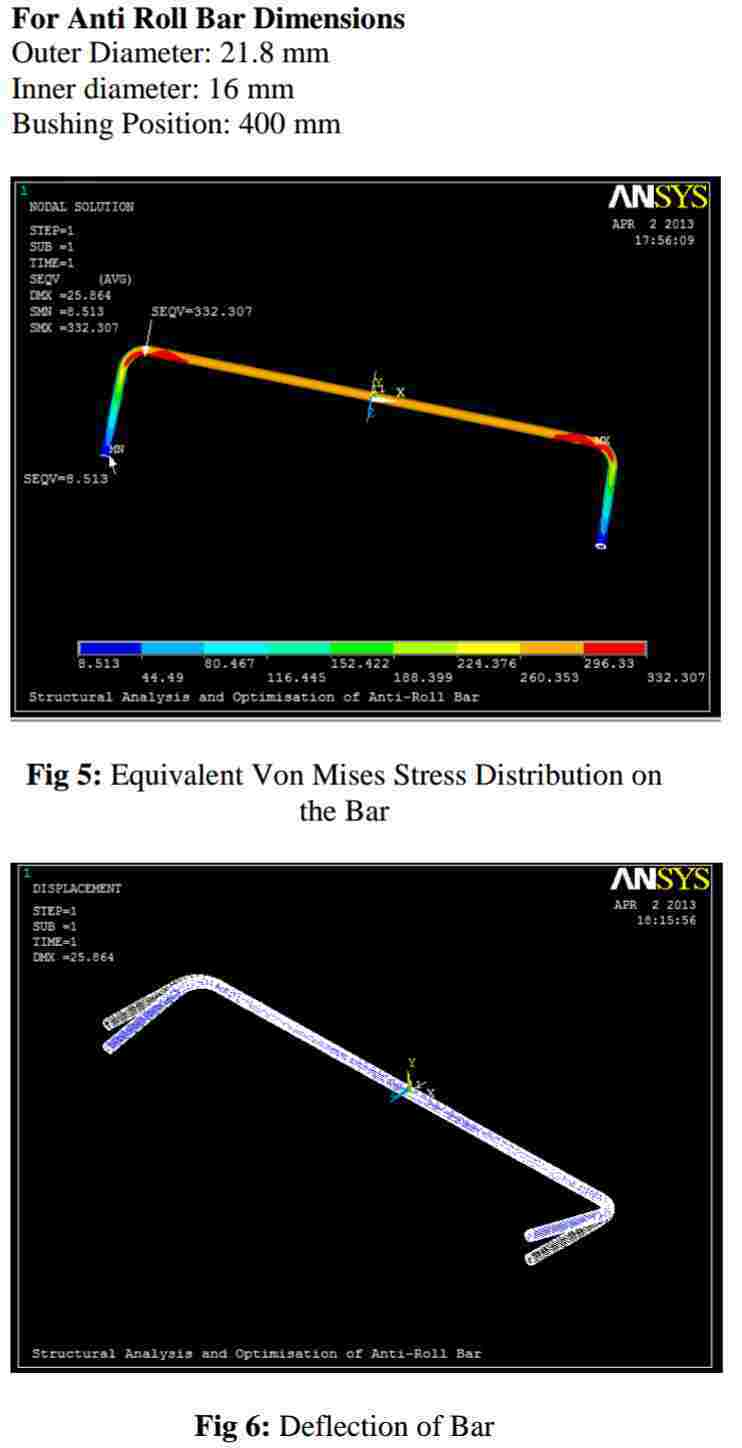
a Sway Bar for my trike, the International Journel of Engineering Research and Application ijera.com vol4, issue 9 showing the stress distribution. Fabricated an adjustable sway bar after calculating polar modulus of elasticity. Finite adjustments can be made after real driving conditions are analyzed.
______________________
dedow
Tadpole
Post by dedow on Mar 19, 2018 at 3:30am
I am a mechanically inclined senior citizen building a reverse trike out of scavenged parts. My rack and pinion steering has been altered to fit the width of my design... is it possible to use different length tie rod connectors. I'm having trouble with one-wheel wanting to roll under itself.
______________________________
Liteway
Exalted Member
Post by Liteway on Mar 23, 2018 at 1:24pm
Hello dedow.
More info please. By "roll under" do you mean the outside of the outside tire wants to roll over on its sidewall in a turn?
Generally speaking, the tie rod lengths should fall somewhere between the lengths of the upper and lower control arms, if we are talking wishbone suspension here.
__________________________________
Read more: reversetrike.proboards.com/thread/343/vehicle-engineering-visualized?page=3#ixzz5YiULDbVj
captainamerica
Exalted Member
Posts: 328
Mar 6, 2012 at 10:09pm
Post by captainamerica on Mar 6, 2012 at 10:09pm
Hi all,
This is the start to what will hopefully be a helpful suspension design thread. At some point it may expand to general trike design but for now I am going to concentrate on just the suspension, and more specifically the double wishbone layout. I will be incorporating lots of pictures because I myself am a visual learner and I feel that words can not do justice in explaining mechanical systems nearly as well. Please inform me of things that you like or dislike, so that I can make edits and changes for future posts. If you see something wrong or something I have missed, please point it out. Enjoy.
-Andrew
So first off is the basic suspension layout used on pretty much every modern open wheel race car in existence, barring formula Vee maybe, and a lot of the reverse trikes on here. The system consists of one upper and one lower A-arm (named for their distinct shape). These arms are used to attach the wheels to the chassis. Unequal length arms are used to keep the wheel relatively in the same position with respect to the ground no matter what the chassis is doing.
This brings us to our first term of the post, Camber Angle, this is defined as the angle the wheel makes with the ground. Camber is broken down in two parts, static and dynamic. For now we will only consider static, because that is what I have a visual of. When the top of the wheel is closer to the chassis we call it negative camber and the opposite sign is used in the opposite direction. In this picture the wheel is about 4.5 degrees off from the vertical towards the chassis so this would be negative (-4.5) degrees of static camber. Static camber is measured when the vehicle is static, preferably wet (fuel, oil, coolant) and with the driver on board. Negative camber is preferable for the same reason we lean bicycles when turning them at any decent speed, it makes the tire "dig" into the pavement when a horizontal side load is applied. However, if you have to much angle on a light vehicle you will actually lose traction in the corners (and in the straights) because the tire contact patch becomes too small. Another downside to incorrect camber angle is that you will wear your tire tread abnormally, I was running to much on the Spartan when I first built it and within 100 miles I could see a difference between the right and left sides of the the tires. Camber Angle is an adjustable quantity, altered by changing the length of the A-arms, usually the top A-arm as this is not linked to the pushrod so it is less complicated.
The next important term is Kingpin Inclination Angle and Scrub Radius. Simply put Kingpin Inclination Angle is the angle between an imaginary line drawn through the outboard A-arm mount points, looking from the front view, and the Camber Angle line. Some of you are probably wondering why it can't just be parallel to the camber angle, it very well could be but read on. The reason it is inclined relative to the Camber Angle is because the wheel actually rotates on the Kingpin Inclination line. The distance from the center of the bottom of the wheel to the point where the Kingpin Inclination line crosses the the bottom of the tire is a measured quantity called Scrub Radius. Why is this a radius and not a distance you ask, from the top view it is the radius that you have to drag the wheel around when you turn. For us visual folk, hold your hands out in T, as if your calling a "time out", with your left hand fingertips pushing into your right hand palm and your thumbs vertical. Now try to rotate your left wrist around the axis your left thumb creates while keeping the T shape. In this case your right hand is the tire and your left hand is the scrub radius. This is how the tire will move if your Kingpin Inclination angle is parallel to the Camber angle. This radius (the length of your left hand from thumb to finger tip) is known as the Scrub Radius because you are literally "scrubbing" the ground with your tires as you turn. The larger this radius is the harder it is to turn and the more you "feel" the steering system at speed. For those of us without power steering, this is a bad thing at low speed. The scrub radius in the picture is .164". Kingpin Inclination and Scrub Radius are design features of the suspension and are unchangeable without physically changing parts (usually by shimming one of the upright suspension mount points; upper, lower, or both). The design in the picture is capable of being shimmed on the upper mount only, and beware shimming at a mount point will also alter your camber angle so both need to be adjusted at the same time in that design.
Last Edit: Oct 1, 2014 at 8:31pm by captainamerica
Mar 7, 2012 at 12:34am
Post by captainamerica on Mar 7, 2012 at 12:34am
The sister terms to Kingpin Inclination and Scrub Radius are Castor Angle and Mechanical Trail. Castor Angle is the angle between the vertical and an imaginary line drawn between the outboard suspension mounts, this time from the side view. Mechanical trail is the distance measured from where the Castor line crosses the ground plane to where the vertical line passing through the center of the wheel crosses the ground plane. In reality the center of the tire contact patch sits slightly past center opposite the direction you are traveling so the real trail is a bit longer then the calculated trail. This difference is know as Pneumatic Trail. The larger the trail the more resistant the wheel will be to steering input and the more it will want to self align to its point of minimum energy (straight forward). Lighter vehicle like trikes tend to turn more easily so having a decent amount of trail to help it go straight is a good thing. The heavier the vehicle the more it wants to continue on in a straight line and so the less trail is needed, and even negative trail (negative castor) is sometimes used to make the car more responsive. This is like making an aircraft that is so unstable a computer is needed to make it fly straight, the instability makes it extremely responsive.
The Castor line does not need to pass through the center of the wheel, which allows the angle and the trail to become independent of each other. However just by thinking about this for a minute we realize that moving the Castor line from center will cause a scrubbing effect when turning because the wheel center rotates around the Castor line. This is not something that is ever done to my knowledge.
Another important term is Toe Angle which is the static position of the wheels (front or rear) at ride height and with no steering input. This can be used for all sort of good and bad things. Toe IN is when your aim the wheels at each other in the forward direction, and Toe OUT is when you aim the fronts of the wheels away from each other. This is usually measured as a length and not an angle, although the angle can be calculated very easily from the length if the tire/rim radius is known. More pictures and info on this later.
________________________________
jim99
Exalted Member
Posts: 116
Post by jim99 on Mar 7, 2012 at 8:16pm
Hi Andrew,
Great information that you are sharing with everyone. Hopefully everyone is reading this thread.
The positive of having Scrub Radius is it helps to provide steering feel and feedback to the driver.
If you have zero scrub radius (called centerpoint steering) the driver will complain that the car is "darty", the steering reacts too quickly and that there is very little steering effort and feedback to the driver.
The negitive effect of scrub radius is that it will cause the tires to build heat and increase tire wear.
So that means we need to find a happy medium.
The only feedback I can give is that I built a trike with about 1/4" of scrub radius. Very unpleasant to drive or ride in.
This winter I have rebuilt the front end and now have about 1 1/2" of scrub radius. Once the snow is gone and I have driven the trike with the new front end I will update as to if I feel I have too much or too little scrub radius.
Jim
___________________________________________________
Post by captainamerica on Mar 10, 2012 at 3:29am
Thanks for the input, I really haven't driven any vehicles with adjustable scrub radius. So I have no idea what it feels like. Good to know.
___________________________________________________
Post by captainamerica on Mar 10, 2012 at 4:23am
Quick Detour to the Brake World
Brake Pedal to Caliper Calculations
I use Wilwood brakes because they are cheap, and the company provides extensive information about all their products. This is a break down of the front brake force calculation I used to size the master cylinders and see if my pedal size was right. The brake pad material determines the coefficient of friction between the pad and the rotor. Wilwood street pad material comes in three forms BP-10/20/30. I chose to start with BP-10 because its cheap. I used the point of 400F for the coefficient determination because its where BP-10 and BP-20 Cross. This was arbitrary, once I have pad temperatures from testing then I will reapply the calculation. The spartan trike uses the following calipers and master cylinders.
Wilwood Forged Dynalite Info
wilwood.com/Calipers/CaliperList.aspx?subname=Forged%20Dynalite
Wilwood 7112 Brake Pad Info
wilwood.com/BrakePads/BrakePadsApp.aspx?compound=BP-10
Vehicle Calculations
Vehicle Weight = 1100lbs (estimated currently)
CG Height = ~16in
Wheelbase = 95in
Tire Info = 205/40R17
Tire Width = 205mm/25.4(mm/in) = 8in
Tire Wall Height From Rim = 8in*(40%) = 3.2in
Total Radius = (17/2)in+3.2in = 11.7in
Wheel Radius Under Load = 11.7in - .4in (estimated) = 11.3in
Tire Coefficient of Friction = CfT = 0.8 (average tire)
Front/Rear Weight Distribution = 55/45 (estimated)
Load on Front Wheels (2) = 1100 * (55%) = 605lbs
Static Load on Rear Wheel (1) = 1100 - 605 = 495lbs
Static Load on Each Front Tire = 605lbs/2 = 302lbs
Acceleration Force
Max Acceleration = ~0.5G
Load Transfer Under Acceleration at 0.5G = (0.50G*1100lbs*16in/95.5) = 92lbs\
Total Load on Rear Wheel = [(1100lbs*.45)+92lbs] = 587lbs
Max Traction Acceleration Torque = Traction Force * (CfT) * Wheel Radius Under Load = 587lbs*(0.8)*(11.375in/12in)ft = 469 lb-ft
This sections solution is questionable by me, use at your own risk.
Braking Force
Load Transfer Under Braking at 0.8G = (0.80G*1100lbs*16in/95.5) = 147lbs
Total Load on Each Front Wheel = [(1100lbs*.55)+147lbs]/2 = 376lbs
Max Traction Braking Torque = Traction Force * Wheel Radius Under Load = 376lbs * (11.375in/12in)ft = 330 lb-ft
Total Load on Rear Wheel = [(1100lbs*.45)-147lbs] = 322lbs
Max Traction Braking Torque = Traction Force * Wheel Radius Under Load = 322lbs * (11.375in/12in)ft = 305 lb-ft
Front Caliper Calculations
Number of Pistons = 4
Piston Bore Diameter = 1.375in
Total Piston Area = PI*Radius^2 = PI*(1.375in/2)^2 = 1.48in^2
Total Piston Area Per Rotor = 1.48in^2 * 4 (# of Pistons) = 5.940in^2
Coefficient of Friction (Cf) = 0.42 (BP-10 Pad@400F)
Rear Caliper Calculations
Number of Pistons = 2
Piston Bore Diameter = 1.25in
Total Piston Area = PI*Radius^2 = PI*(1.25in/2)^2 = 1.23in^2
Total Piston Area Per Rotor = 1.23in^2 * 2 (# of Pistons) = 2.46in^2
Coefficient of Friction (Cf) = 0.42 (BP-10 Pad@400F)
Pedal and Master Cylinder Calculations
Pedal Length (L1) = 11 in
Bias Bar Point (L2) = 4 in
Pedal Mechanical Advantage = L1/L2 = Ag = 2.75
Pedal Motion Ratio = L2/L1 = .363
Pedal mechanical advantage is how much more force I get at the master cylinder then the foot, and the motion ratio is the inverse or Ag and it determines how far the master cylinder will compress for any motion in the pedal. If I move the pedal contact point 1" with my foot I will move the master Cylinder ~.363".
Master Cylinder Size Determination
The larger the bore the harder it will be to push the pedal, some people like to have an extremely stiff pedal while others want to be able to feel the pedal move so they can better determine the required force to stop. I used 3/4" the front and 5/8" on the rear bore on. The smaller the master cylinder the more responsive the brake will be as line pressure will increase much faster.
Master Cylinder Bore Diameters (Shown for Comparison)
D= 5/8 = .625in A=.307in^2
D= 7/10 = .7in A= .384in^2
D= 3/4 = .75in A= .442in^2
D= 7/8 = .875in A= .601in^2
Volume of Fluid Used at Front Calipers (2) = Distance Traveled * Total Piston Area = .01in * (5.940*2)in^2 = .1188in^3
Distance Master Cylinder Moves = .1188in^3/0.601in^2 = 0.198in
Foot Motion Required to Move Cylinder that Far = Distance / Pedal Motion Ratio = .198in/.24 = .83in
Volume of Fluid Used at Rear Caliper (1) = Distance Traveled * Total Piston Area = .01in * (2.46)in^2 = .0246in^3
Distance Master Cylinder Moves = .0246in^3/0.307in^2 = 0.08in
Foot Motion Required to Move Cylinder that Far = Distance / Pedal Motion Ratio = .08in/.24 = .83in
You can work out this set of equations until you find a distance of pedal motion that works for you. Smaller diameter master cylinders will give larger pedal motion. Changing the pedal motion ratio can also be toyed with the allow you to hit any pedal distance you want.
Brake Torque Calculation
Applied Foot Force = FA = 100lb (Assumed, I have yet to measure this)
Force Applied to Master Cylinder = FA*Ag = 80*2.75 = 220lb
Bias To Front Wheels = 50/50 (Bias Bar Centered)
Line Pressure for 3/4" Master Cylinder = 220lb*(50/50)/0.442in^2 = 497 psi
Line Pressure * Piston Area per Rotor = Force Applied to Rotor = 497psi * 5.940in^2 = 2956lbf
Force Applied * Cf of Pad = Brake Force = 2956lbf * .42 = 1241lbf
Front Brake Force * Rotor Average Radius = Brake Torque = 1241lbf * (10.375in/12in)ft = 1073 lb-ft
Line Pressure for 5/8" Master Cylinder = 220lb*(50/50)/0.307in^2 = 716 psi
Line Pressure * Piston Area per Rotor = Force Applied to Rotor = 716psi * 2.46in^2 = 1762lbf
Force Applied * Cf of Pad = Brake Force = 1762lbf * .42 = 740lbf
Front Brake Force * Rotor Average Radius = Brake Torque = 740lbf * (3.70in/12)ft = 228 lb-ft
So from this calculation I can see I need to do a little work, I have approximately one and a half times as much brake force as the wheel can theoretically handle (228/226 = ~1). This is close enough for me to test out and see if it works in the current configuration.
_________________________________
Oct 1, 2014 at 9:54pm
Post by captainamerica on Oct 1, 2014 at 9:54pm
Next up is Ackermann Angle, this is the angle between the center line of the car (from the top view) and the imaginary line drawn from the steering mount point to the closest A-arm mount point. The closest mount point depends on where the steering point is located on the upright. In the picture it is in the top front position. The steering rack plays an important part in how well the ackermann setup will work, in the standard case in which the rack is in front of the wheels (as shown), moving the rack away from a position that makes the steering tie rods perpendicular to the direction of travel (in the top view) will decrease how much effect ackermann steering has. In the case shown the steering rack is moved forward to fit the driver and so the ackermann angle is actually more then "full ackermann" to compensate.
Ackermann steering is usually used to make the inside wheel rotate more then the outside wheel in a turn, the radius that each wheel takes should be matched to the turns that the vehicle will be making, this is easier to calculate for race cars on fixed tracks with known radius curves. Full Ackermann is a term used to describe when the left and right Ackermann lines meet directly over the rear axle center line. Ackermann angle is a bit subjective as far as what works. Racecars sometimes use reverse ackermann to create more favorable slip angles with their tires.
Something to note, we can see that there is empty space in from of the steering bolt point which could allow us to move that point forwards on the upright to help make the steering tie rod at less of an angle but this would in turn reduce the amount of total steer angle allowed because of the increased distance from the kingpin axis. This is all about compromise and knowing what we need, how hard do the wheels need to turn, I suggest going out to your daily driver, turning the wheels all the way to a left or right lock and measuring the angle they make, I did this with two 2x4s and a protractor. If you measure both wheels you can get an idea of the amount of ackermann used by the major manufactures.
In the case of a mid height steering mount you would want to calculate how far you are from the 3-D line created by the castor and kingpin lines.
Below is a picture of a theoretical car making a turn on a 10 foot radius, we would only see this in parking lots and u-turns maybe but I did it this way so you could see all the numbers clearly. As you can see the center of the turn is shown as the point the rear axle passes through, this is good enough for this example. Perpendicular lines are then drawn to the center of the chassis (11 degrees) which is that actual direction the car is headed and then one each to the front wheels showing the difference in required steering angles for a "perfect" turn.
NOTE: The difference in angle between the direction the chassis is traveling versus the direction the wheel is aimed is the slip angle of the wheel, this is over simplified here.
0 Degree Ackermann in static and steering. So this example is shown to show you why ackermann is used. We can see that the front suspension is shown in plan view, for simplicity I did not take into account kingpin or caster in this model. The scrub radius is 2 inched, the top and bottom A-arm attachments are directly over one another and the steering attachment is 5" in front. After I did the setup I added in the 18" wide steering rack and made sure it was in a position so that the steering tie rods were very close to horizontal. We can see that when we turn both wheels turn almost the same amount, we lose a little due to the scrub radius moving one wheel back and the other forward but its still pretty good. However we know from the previous picture that one or both of the wheels will be dragging on the pavement because they are not aimed along the line of travel for the turn we are attempting.
.15 Degree Ackermann in static and steering. Now I have taken the same setup, added 15 degrees of ackermann to the setup and adjusted the steering tie rod length accordingly, this is crucial otherwise your wheels would not be straight when you went straight, this will not be repeated but it is done in all of the following examples. We can see that we are very near the hoped for ackermann angles using this 15 degree number. It is not shown here, but at 15 degrees and this wheelbase as shown in the first picture the ackermann is just slightly past full, so the lines intersect just in front of the rear axle center line. It is crucial when measuring your ackermann intersect that the toe angle be zero degrees as it directly adds to the ackermann in this calculation.
2" forward position of the steering rack static and in turn. So now the steering rack is moved forward 2". We can see that this has negatively affected our outcome, we need to add more angle to compensate for this, This is very similar to the setup on the Spartan, which works well but I had to use a larger angle which has turned out really well. This angle has limits though, most noteably the rim and the brake rotor, these box you in when you put your steering point at the top or bottom of your upright. However because of the castor angle, as in my setup, the top front and bottom rear become the best places as the upright leans away from these locations giving us more room to play. NOTE: This setup occurs much more often because performance vehicles usually want to minimize wheel base to assist with minimum turn radius and the rear wheels are kept inline with the transmission outputs to minimize power losses from the drive train. The last generation of indy cars (2000s) used approx. 3" of forward position of the rack.
2" backward position of the steering rack static and in turn. In the case that your car is to small and you want a longer wheel base, this can occur, but it is not preferable to straight in my opinion and is harder to package. It can be seen to have a positive effect on your ackermann allowing you to run less angle, in the same way that moving the rack forward can have a negative effect.
I will add the same analysis for a rear mounted rack in the near future.
NOTE: An interested case that occurred on the Spartan when I first got it rolling. I was using the water jet cut steering attachments which have zero ackermann built in, my rack sits about 3 inches forward form horizontal and this caused a negative ackermann angle when turning. The inner wheel would barely turn and the outer wheel would turn drastically making moving the thing around the shop a total pain.
_________________________________________________
Post by captainamerica on Oct 4, 2014 at 12:41am
This is the follow up post to the ackermann steering design post above. Here we are looking at a rear mounted steering rack, the vehicle is now going to the opposite direction for simplicity on my end.
0 Degree Ackermann. This is very similar to the front mounted setup, almost exactly the same steering angle for both tires in a turn just as we would expect.
15 Degree Ackermann. This shows an immediate advancement in the right direction. The real down side of having rear mounted steering is that you almost always have to put it on the bottom of the chassis which is alright but then the steering column has to go between your legs, which can be less then pleasant and your column as to make a 90 degree turn usually.
15 Degree Ackermann. Here I have moved the steering rack backwards in the chassis relative to the steering mount to the uprights. This helps the ackermann difference more then the following change and is actually better then the standard.
15 Degree Ackermann. Here I have moved the steering rack forwards in the chassis relative to the steering mount on the uprights. The outcome is not as good as the straight horizontal tie rods which was expected. This is the reverse of the outcome of the front mounted rack just as would be expected since everything is basically mirrored across the front axle plane. The further forward you but the steering wheel the tighter the turn the column will make so it may be a requirement to move the rack to a position that actually works and hopefully allows the column not to bother your legs to much. It is also very simple to move the wheels (changing the wheel base) and alter your setup. If you are using some sort of stock car suspension then the A-arms are probably already fixed and you are now just needing to come up with a compromise for the steering system that works for you as the driver.
________________________
skifffz1to3
Full Member
Posts: 101
Post by skifffz1to3 on Oct 4, 2014 at 9:06am
This is awesome. You continue to pour 10 gallons of information into a 5 gallon can! However, in my own case, I've got my can sitting in a 500 gal washtub (internet/this forum thread) so I can save, and re-pour as needed to absorb it all. Keep pouring!
________________________________
captainamerica
Exalted Member
Post by captainamerica on Feb 14, 2015 at 10:38pm
I asked myself the same thing.
_________________________
Liteway
Exalted Member
Post by Liteway on Feb 7, 2016 at 10:49am
This is a great post that must have taken considerable time to compose. While I find it hard to absorb it all, It's a help to have this post for reference for particular questions right here on the site.
________________________
captainamerica
Exalted Member
Post by captainamerica on Mar 27, 2016 at 1:56pm
Finally getting around to adding to this.
Roll Center is up next. The roll center of an independent suspension design is found by following the lines of the A-arms from the front view until they intersect and then draw a line from that intersection (also known as the instantaneous center) back through the center of the contact patch, when this is done to both sides of the suspension, the line through the wheel contact patches will cross (on the center of the vehicle in a road course setup). For an oval track this wont be true. Also note that parallel suspension points will never intersect and this analysis can't be done on them, however unequal length suspension geometry can only be parallel at one point if at all.
The suspension shown below just hit a bump, pushing the front wheels two inches up, I just did this so that it was easier to separate the line through the contact patches, normally I would do this by varying the ride height and leaving the wheels fixed to the ground.
In my experiments with this setup sketch I was surprised to find that the roll center does not move with relation to the chassis as the wheels move through their motion. Whatever you set as the static roll center height it will stay generally around that point, mine moved 1/10th of an inch from my static height of -0.50 below ground over the +/-3" range of motion. Just to reiterate, this is talking about the measured distance from the chassis to the roll center, not the distance from the fixed ground plane, both are shown in the drawing.
If we find both the front and rear suspension roll centers, then a Roll Axis can be drawn through the two roll centers longitudinally for the chassis and it will show you the axis that the car will roll around. This is not that simple since as the car rolls the roll center moves. In a three wheeler the rear end is simple, the roll center is at the center of the contact patch in the rear on the ground plane. Generally speaking from what I have seen and read a lower roll center in the front is desirable giving the roll axis a slight angle down towards the front. What this means for us reverse trike folks is having a roll center below ground at static ride height would be a good starting place.
The line between the CofG and the roll center is a moment arm which determines how much advantage the vehicle has over the resistance of the suspension. Just imagine a pry bar arcing over to pull a nail out, the further your hand is from the nail the easier it is to pull. The more mass you have the more the car will want to roll and the further that mass is from roll center the easier is will get the car to roll. I do not know the results of putting the roll center on top of the CofG or extremely far under ground, max and min roll arm lengths, but I would guess that any gain that came from that design would cause an even bigger problem elsewhere.
SIDE NOTE: A friend of mine awhile back designed a suspension system where the upper and lower A-arms crossed one another, the upper chassis mounts connected to the lower ball joint etc, this was his plan to get large camber gains from small chassis rolls and then limit chassis roll quite a bit. Not sure how this would ride but it looked pretty interesting on paper.
_______________________________
captainamerica
Post by captainamerica on Mar 30, 2016 at 7:13am
The way it rides is a very non-specific idea that will vary from person to person, but in general I would have to say no you wouldn't want to move the roll center up high as the roll axis would be severely angled upwards toward the front and the driver would have a rather strange feeling for how the car is turning in. If someone wants to try it out I would be more then willing to listen to how it turns out. That being said there is a lot to be said for the amount of camber gain through bump and roll based on the location of the instantaneous center, I am going to do some looking into about exactly how this affects things but the idea is that the further the center is from the wheel in question the less camber gain or change you will see for a motion of the wheel.
_______________________________
endeavor
Junior Member
Post by endeavor on Apr 9, 2016 at 9:12am
It's been awhile since I toured this board. This is an interesting and very intuitive posting. You have done a great job Mr CA in explaining all the things I have learned the hard way :-)
To date I hand built 4 prototype units and rebuilt most of them at least 3 times mostly due to things I learned over the years regarding KPA, caster settings, scrub, turning radius and camber settings. It's such a contrast reading the tech data here regarding all these things then going onto the Spyder site and reading all the postings on Laser alignment to set toe and the perceived great handling improvements. (again a giggle)
One thing I have come across here in the last year has been the importance of tie rod height which I would like to share.
Like the CanAm my design does not use idler arms rather a single tie rod on each side connected to a steering shaft directly. While this is simple and works well one problem is determining where to set the steering shaft / rod connections as far as height. Now if the distance from the lower ball joint to the tie rod location is say 5 inches then the distance at the steering head will have to be slightly less than 5" or in my case I set this at 1/2" less.
Here is the reasoning. during body roll if the steering heat height is higher than the wheel location height then the unit will tend to try to counter steer and attempt self corrections resulting in the unig darting back and forth it will also drift badly in the corners. having the center attachment lower will offer a more gradual and natural positive drift. Feedback is more inline with what is expected and all motions are softened.
I also now build all my own A-arms and found as the scrub is reduced I have to add more caster. Also the caster and camber angles vary with vehicle size and weight.
Another thing with is overlooked by even the "Big Boys" is aerodynamic profile. The large fiberglass enclosures some of the new entries are using are very detrimental to handling along with the larger 17 and 18 inch low and wide profile tires. In essence the center of pressure is moved ahead of the center of balance causing poor handling at high speeds and in windy conditions. It is best to have the nose small along with the tires to minimise the pressure area.
I actually met briefly with an aerospace scientist who filled me in on all this.
Another thing I do which goes completely against the grain and logic of suspension is to use very heavy wheel assemblies. This was not my original desire but as it turned out the easiest and cheapest route to go is to simply use automotive components. Normally you want upspring weight low so the wheels stay on the ground however the unforeseen benefit of the heavy wheels is they add dramatically to the stability in corners as the heavily weighted wheels act as ballast and effectively lower the roll center as described above. This may not be the best on a 4 wheel unit but a 3 wheeler tends to also "woddle" which helps control the tires keeping them planted. I find my trikes will slide in a corner rather than tip so the effect is dramatic. Tire pressure on my setup is 16psi front and 26-30 rear so the tires actually absorb most of the road irregularities.
While I have learned much over the past 7 years and 144,000 miles i just know a fraction and keep learning each day. Thanks for all the great information.
Endeavor Trikes went into production July 2014 and so far 13 units on the road all hand built all customs and it's all good.
________________________________
noahkatz
Junior Member
Joker,
Why do you think ride quality is related to roll center height?
But to answer your question, yes, if the roll center is at the same height as the CG, there would be no body roll in corners, other than from changes in rolling radius of the tires.
The problem with that, at least for A-arm suspension, is that vertical motion of the tires causes them to scrub laterally.
You can see this by visualizing the motion of a virtual suspension arm which you create by drawing a line from the roll center to the center of the contact patch.
____________________________
endeavor
Junior Member
Post by endeavor on May 11, 2016 at 8:50am
In reading all the info here and meganracing I have made some changes to my current design. I was running my A-arms perfectly parallel but have lowered the top A-arm hinge 1.5 inches. I am using one piece tie rods with no idlers so the arc produced by the A-arms and tie rods didn't coincide during movement. Now they seem to. The first thing I noticed during bench test is now the toe adjustments remain consistent during suspension compression and extension so I no longer need to compensate for toe drift.
I have not road tested as I am still assembling but will share any conclusions when the time arrives. I am glad I came across this thread, still more to learn.
__________________________
Page 2
noahkatz
Junior Member
Post by noahkatz on May 14, 2016 at 1:50pm
Right, I still don't understand what ride quality has to do with roll center.
________________________________
captainamerica
Exalted Member
Post by captainamerica on May 14, 2016 at 8:41pm
Alright so I read Joker's question awhile back and didn't really have a good grasp on it, not sure if I do now but it seems to have generated some controversy. My comment would be that while you could make the roll "zero" by putting the roll center on top of the CG, you could also just reduce roll by using an anti-roll bar, want no roll, use a really stiff one. The bar at the front of the Spartan is way to strong but I can tell you that there is almost no roll in that vehicle. I really don't see the benefit to trying to design out the roll of the vehicle completely by moving the roll center, your camber curves would go to Poop I expect among other things. All of that said, ride quality is quite a subjective idea, someone might drive an indy car down a normal road and think that its way to stiff any time it hits a pot hole or bump, yet that same car on a speedway might handle like a dream yet they are the same car. So handling is more important relative to the roads you will be driving, I realize that roll in a trike causes loss of rear wheel contact patch if your using a car tire, but tires especially at lower pressures can handle "camber" and still keep a reasonable contact patch. So I think if you just limit your roll using an anti-roll bar you will find what you are looking for without compromising your suspension design all for one parameter.
_______________________
DaveJ98092
Administrator
Post by DaveJ98092 on May 14, 2016 at 10:51pm
A roll (SWAY) bar of the correct size will work like Andrew said. It makes suspension design a bit easier. The (slight) problem with roll bars is it also limits a independent suspensions independence some what, but do you really need true 100% independent suspension?
I had a Chevy 3500HD dually truck with a SOLID I beam front axle and Kingpins, not ball joints. It would corner with almost any non sports cars in corners. My son had a 85 Toyota SR5 4X4 pickup that had a solid differential axle up front. One day his his Autocross car broke at the track and he asked if he could take the pickup out and give it a run JUST to see. It was in the middle of the slow class of CARs as far as time.
____________________
endeavor
Junior Member
Post by endeavor on May 15, 2016 at 7:25am
You are correct in the assumption an anti-roll bar of sufficient heft would zero out the roll nicely. It would also limit the independance in the suspension. However there are substantial differences between a 4 wheel vehicle and these tadpole designs as far as suspension and cornering dynamics. On a 4 wheel vehicle you can tune your handling and ride characteristics both front and rear. You would be running anti-roll on both ends and 4 wheeler tends to run down the road fairly flat while the individual wheels move quite independently. On a trike things are slightly different as there is not sway stability on the rear as the rear wheel acts as a hinge allowing movement without resistance. All the tuning, anti sway roll center etc is totally up to the front end geometry. Trikes also do something which I call waddle. where the trike body tends to rotate as the wheels encounter bumps as there is not any resistance in the rear to offset this action. Even with soft roll bar and soft suspension this waddle will occur. One does acclimate to this however quite quickly but a newbie tends to feel the trike is moving laterally or dodging sideways when in fact it is just the waddle that offers the illusion of lateral movement. So in general I believe a stiff anti-sway is a good idea as it solves some problems and only slightly exaggerates others.
I am open to other opinions I have done 180's on ideas many times.
_______________________
Liteway
Exalted Member
Post by Liteway on May 15, 2016 at 9:36am
You make some good points I have not seen expressed here before, pointing out there are trade-offs with a thick anti-roll bar, that simply making it super thick may not give the best overall result, there are always compromises to be made.
I would point out the "waddle" will be less apparent the lower the driver is located in the chassis, so its more of a problem with a sit astride trike.
4 wheel road testers sometimes refer to it as "head toss" which tends to be more apparent in high sitting suvs and pickup trucks, particularly if they are stiffly sprung.
__________________________
endeavor
Junior Member
Post by endeavor on May 15, 2016 at 9:50am
Yes I tend to forget most of the builds here are low slung and mine tend to focus more on the higher riding position. Good point. Yet the theory is the same just the perception differs.
One other aspect I have run accross which may or maynot be of interest. Because I don't run idlers on the tie rods the rods are a one piece unit. obviously this poses a small problem as the tie rod arc and A-arm arcs do not coincide. During body roll if the center mount on the steering shaft is higher than the balljoint to tie rod mount on the wheel the trike will tend to overcompensate for lean and drift by toeing in so you end up with an oscillation due to this aspect and the rider also trying to overcompensate. I found that in lowing the center mount position I can effectively slow down this oscillation to a controllable almost unnoticeable amount. For instance my tie rod to ball joint measure is 5" and my steering mount is 1" less so when there is roll the wheels actually toe out just a degree or so softening the drift to a very gradual amount. Raising the mount would cause the old Burt Munro 190mph head shake.
The theory is much the same as cargo ships vs passenger cruise liners. A cargo ship rides low in the water so it is very stable and will resist tip over in heavy seas however the rocking motion will be fierce and quick. A cruise ship rides high so these oscillations are gradual and soft, the purpose is to lessen the likelihood for motion sickness.
________________________
endeavor
Post by endeavor on May 16, 2016 at 11:51pm
OK I finished the latest build tonight. The top A-arm hinge was dropped 1-1/2" in hopes of altering the roll center. While I am sure it worked (the math would support this) I am unable to honestly comment. If all I did was make this change then I could voice an honest opinion however I also changed the A-arm design, shock mounts and even the shock length and the swaybar. With all these changes I can't commit to a report. All I will say is things are good and didn't get worse. The bike handled great before and does now.
You can see the A-arm stance here along with the anti-sway setup - the sway bar was also changed with this build. Camber is set to zero, Caster 8 degrees positive and toe 1/4" positive. Tire pressure is 17psi.
Sideview just for reference. Also a good view of the powercoated items
mtntech
Exalted Member
Post by mtntech on May 17, 2016 at 10:02am
Your tire pressure is interesting. I have been experimenting with lower pressures as well.
____________________________
endeavor
Junior Member
Post by endeavor on May 17, 2016 at 10:09am
BRP recommends 12.5 to 17psi on all the Spyders, of course most people (curbside engineers) are running 25 to 32psi as they can't seem to live with such low air pressure. The end result is a poor handling machine and tire mileage in the 8-9k range. The unit pictured has 22k on the tires and I fully expect 50k min.
A slightly higher pressure may be good for all out racing if you can control the bounce however in general tire patch is a result of air pressure vs applied weight.
At least this has been my findings regarding the matter.
One thing you may notice is the grill is pretty open so what air doesn't go around can pass through this reduces the forward pressure area and aids in high speed control and efficiency.
Last Edit: May 17, 2016 at 10:12am by endeavor
___________________________
Liteway
Exalted Member
Post by Liteway on May 17, 2016 at 6:19pm
I am struck by how much mass appears near, over the top or even behind the rear tire. Thats even before accounting for the mass of the driver, the high perched passenger and luggage seeming everywhere but where it might help balance. Track is not very wide. This will slide before it tips?
I will concede looks can be deceiving, but it looks unstable.
____________________________
endeavor
Junior Member
Post by endeavor on May 17, 2016 at 10:00pm
It is surprisingly stable and you are right looks are deceiving but the mass is all plastic the heavy materials are at axle height so even with a passenger it will slide before lifting a wheel. Keep in mind each front wheel also weights about 65lbs due to the heavy rotors and calipers (Chevy II) That really keeps the wheels planted.
I had some handling issues today and realize I was in a hurry and forgot to tighten the steering shaft lower bearing mounts so I had substantial play in the bars. Snugged her up tonight and it really handles well. Can't commit for sure but it appears there is slightly less lean so maybe the A-arm change did work OK.
__________________________
mtntech
Exalted Member
Post by mtntech on May 18, 2016 at 9:05am
What is the weight of your completed trikes?
_____________________________
endeavor
Junior Member
Post by endeavor on May 18, 2016 at 9:59am
The kit adds 140lbs to the base machine most of that is in the wheels which does sort of defy standard suspension ideals however it also greatly aids in stability as the wheels act as ballast weights. This was something unplanned and just happened due to product choice. This is also the reason my trikes are rated higher than CanAm in cornering tests as the CA will tip without VSS where mine stay planted. It has little affect on actual suspension dynamics mainly due to the low inflation rates. Tires being the primary suspension component.
Weight seems to be a concern mainly due to auto advertisers promising better fuel economy with less weight however this mostly applies to stop an d go as you well know the main fuel robber is not weight but air resistance. This is why autocycles like Elio can claim 80+ mpg. It is something I see here and on other RT forums is the desire to build in a streamlined body shell - it's a good plan.
The GL1800 which is the heaviest bike around comes in at +- 1100lbs complete after the build
Last Edit: May 18, 2016 at 10:01am by endeavor
_______________________
Liteway
Exalted Member
Quote
May 18, 2016 at 9:59am endeavor said:
The kit adds 140lbs to the base machine most of that is in the wheels which does sort of defy standard suspension ideals however it also greatly aids in stability as the wheels act as ballast weights. This was something unplanned and just happened due to product choice. This is also the reason my trikes are rated higher than CanAm in cornering tests as the CA will tip without VSS where mine stay planted. It has little affect on actual suspension dynamics mainly due to the low inflation rates. Tires being the primary suspension component.
Weight seems to be a concern mainly due to auto advertisers promising better fuel economy with less weight however this mostly applies to stop an d go as you well know the main fuel robber is not weight but air resistance. This is why autocycles like Elio can claim 80+ mpg. It is something I see here and on other RT forums is the desire to build in a streamlined body shell - it's a good plan.
The GL1800 which is the heaviest bike around comes in at +- 1100lbs complete after the build
end Quote
Your take on the effects of low tire inflation are certainly unconventional, and it's an interesting topic that I do not recall having been taken up elsewhere in the forum, despite it having a big influence on chassis behavior. Thanks for bringing it up for discussion.
I had mostly assumed, based on what I thought I knew, that the best inflation for dry tarmac was largely just a compromise with the ride harshness to be endured vs all other aspects of performance, that the flexible sidewalls that resulted from low inflation gave a cushier ride at the expense of greater rolling resistance and tread stability which in turn resulted in soggy handling, rapid uneven tread wear and increased fuel consumption.
Based on that and the low tire loads imposed on my very lightweight trike I rather arbitrarily selected 27/32 psi as my normal inflation.
Not very scientific of me, but those inflation pressures left me little to complain about the trikes handling, though it does ride a bit harsh, and the rear is a little loose under heavy throttle in tighter corners. I put tire pressures out of my mind and concentrated on other suspension tuning methods.
So now I read your take, and I was finally inspired to do serious testing of juggling pressures while every thing else remains the same.
Thanks for a fun afternoon, as I repeatedly returned to my favorite series of local tight turns to check the effects of the incremental changes.
16/28 psi.
(as compared to my normal 27/32)
Handling slightly more sluggish, with slower turn-in and much higher effort required, particularly noticeable at parking lot speeds.
In really pushing it through the turns, more body roll was apparent with a tendency to run wide through the corner (understeer) and slip at lesser speeds. The ride did improve by not so much as I expected. I would attribute that the trikes very low unsprung weight which allows the wheels to follow the bumps without asking for so much compliance from the tires. The tire/ wheel assembly weighs 14 lbs as opposed to your typical aluminum wheeled compact which is about 3 times that. I also have aluminum hubs and calipers along with small discs.
32/38
Not much change from 27/32 with ride and front end behavior about the same but with a bit better responsiveness. The biggest difference came at the rear where it stays better planted coming out of the corners with noticeably less wheel spin.
As for wear at the front with 10K of aggressive driving, I Don't have enough to project their ultimate life, but they already show a bit of weather cracking after 10yrs so that will be the reason they will ultimately have to be replaced.
I am hoping the discovery that the back tire spins less in tight corners with higher pressures will extend its life a bit as it is wearing pretty fast.
___________________________
endeavor
Junior Member
Post by endeavor on May 22, 2016 at 3:37pm
I can only speak of my own discoveries related to my specific configuration so you are right to assume the best fit will be one you devise. Part of the difference may be in rim type as I am running 6.5 inch wide rims with a narrow 165x60x15 tire so they are overstretched. This offers more lateral control. I am currently running into some mishandling issues with bikes that have the narrow 3" wide rear rim as I have to run a 175x70 tire which is just the opposite. That configuration causes a lost of side to side movement so the trike tends to jiggle from side to side especially in windy condition. Unless I can find a stiff wall tire like a run flat in the correct size I may have to go to a MC tire on the rear on those bikes. Most of the large asian tour bikes run a 5.5 inch rim on the rear so a standard 205 tire works very well with minimal side drift.
What I found on front tires is anything over 20psi causes tire bounce and center wear so lower works for my setup pretty well.
___________________________
Liteway
Exalted Member
Post by Liteway on May 22, 2016 at 7:13pm
Right. The trikes built here are so different in specification, that it would be highly unlikely that any 2 would work best with the same pressures. Even then , the qualities the builder is looking for will be different. Just as for example, one might be wanting a good ride and interstate stability, while another wants responsiveness and grip.
Not sure what you mean by bouncing; the wheel following sharp bumps up and down or overshooting them with the tire actually leaving the surface? The former would define proper suspension action, the latter needs better shock control. Or maybe you are referring to oscillations occurring after the bump. Again an indicator of under damping.
What kind of tires wear the center first with 20lbs in them? Most are designed the run near twice that. As I said, I have a very light trike and run 27 in the front and 32 in the rear. Both are wearing evenly across the surface. I should think running with 20 would wear the edges more quickly, especially as that would allow the edge to roll under when cornering.
I suspect that BRP recommends such low pressures and has Kendra deliver tires specifically designed to run at low pressures in order to limit cornering grip and promote under steer to discourage riders from approaching tipping speeds as a backup for the electronic nannies. OK, just my opinion. No facts there.
Most testers complain of slow handling and quick intervention of the nannies when testing the Spyders and I cannot help but think the under inflated tires are a factor in that.
Photos removed 11/12/16 to save data limits.
This is after 10k of hard use. Sorry for the repetition to those who have looked at my build posts.
_______________________
noahkatz
Junior Member
Post by noahkatz on May 24, 2016 at 2:24pm
Quote
May 14, 2016 at 8:41pm captainamerica said:
I really don't see the benefit to trying to design out the roll of the vehicle completely by moving the roll center, your camber curves would go to Poop I expect among other things.
end Quote
The biggest conundrum is suspension design is the ride/handling compromise.
The crux of this is that the suspension compliance needed for good ride compromises handling, because the resulting roll in cornering causes camber changes, uses up suspension travel, and the dynamic instability of the sprung mass sloshing around.
The reason for this roll is low roll center.
So IF there were a suspension that had high roll center (at the CG) without issues like the camber change and lateral scrub that wishbones give, the ride/handling compromise would be eliminated.
I've come up with a couple but the geometry is klutzy - lots of links, some very long that make packaging difficult.
May 14, 2016 at 8:41pm captainamerica said:
Quote
All of that said, ride quality is quite a subjective idea, someone might drive an indy car down a normal road and think that its way to stiff any time it hits a pot hole or bump, yet that same car on a speedway might handle like a dream yet they are the same car.
end Quote
noahkatz
That just says that a car that handles really well rides poorly.
Ride quality is not really subjective, in the sense that it's been established that a suspension frequency of 1 - 1.5 Hz is considered comfortable by the vast majority of people, whereas sports cars are in the range of 2 - 2.5 Hz; note that double the frequency corresponds to 4X stiffer.
__________________________________
noahkatz
Junior Member
Post by noahkatz on May 24, 2016 at 2:29pm
DaveJ98092
May 14, 2016 at 10:51pm DaveJ98092 said:
Quote
I had a Chevy 3500HD dually truck with a SOLID I beam front axle and Kingpins, not ball joints. It would corner with almost any non sports cars in corners.
end Quote
noahkatz
The only reason for having suspension is to deal with bumps; on smooth roads suspension type hardly matters.
I bet the track was smooth and your story would change on a bumpy surface.
Liteway
May 22, 2016 at 7:13pm Liteway said:
Not sure what you mean by bouncing...
My guess is all that unsprung mass oscillating on the tire spring.
What kind of tires wear the center first with 20lbs in them? Most are designed the run near twice that.
Other things being equal, half the weight (trike vs. car) means half the inflation pressure for the same size contact patch.
__________________________
noahkatz
Yep;a large unsprung weight has to be controlled with stiffer shock valving and this only adds to the ride deterioration caused by the heavy unsprung mass's inability to accelerate upward rapidly in response to a bump which in turn moves sprung mass along with it . Result: you and the chassis become part of the suspension or tied more closely to it.
In response that a trike that only weighs half of what a car weighs (at a given corner) needs only half the tire pressure to maintain contact patch sounds ok in theory.
There are a lot of variables with respect to the tire's construction and tread profile.
In my case, it's hard to find data on a 165/70r10 as not many cars use or have used it.
But going to the BMC Mini Cooper forums, the consensus seems to be 26 or 27 lbs up front is good for the street with considerably more for competition.
I am only ball parking figures here, as trying to be precise would be delusional.
Mini with driver aboard weighs about 1650 with 60 percent up front or 495 on each front corner.
My trike with driver loads each front with 193 . So the best pressure for maintaining the same contact patch as the mini drivers have would be 193/495=.39
.39x26lbs = 10.4 lbs. Interesting.
End of page 2
endeavor
Junior Member
Post by endeavor on Jun 17, 2016 at 11:02am
To clarify my comment on "tire bounce" Tire inflation rate is simply the amount of pressure required to form a proper footprint. Most tires I use are rated for a max load of 1350 lbs and a recommended pressure max of 35 psi. Now decrease the load and you must decrease the pressure or the footprint will become to small and the tire will tend to bounce. Think of a basketball - inflated hard as a rock, it will absorb little energy rather transfer this back into movement and the ball will bounce back almost as highly as initiated. Lower the pressure and the ball collapses and absorbs so much energy that it hardly rebounds.
Also in suspension dynamics the primary suspension component is not springs rather the tire itself. Whatever the tire can not handle is transferred to the spring and it's action controlled by the shocks.
The #1 purpose of suspension is to simply keep the wheel on the ground. Too stiff a spring and the wheel will skip over bumps, too soft and the suspension will top out. Improperly inflated tires will place greater demands on this control and will transfer an excess of shock stress to the secondary suspension system.
And that's all I got to say about that.
_________________________
joe
Full Member
Post by joe on Nov 9, 2016 at 4:05pm
a Sway Bar for my trike, the International Journel of Engineering Research and Application ijera.com vol4, issue 9 showing the stress distribution. Fabricated an adjustable sway bar after calculating polar modulus of elasticity. Finite adjustments can be made after real driving conditions are analyzed.
______________________
dedow
Tadpole
Post by dedow on Mar 19, 2018 at 3:30am
I am a mechanically inclined senior citizen building a reverse trike out of scavenged parts. My rack and pinion steering has been altered to fit the width of my design... is it possible to use different length tie rod connectors. I'm having trouble with one-wheel wanting to roll under itself.
______________________________
Liteway
Exalted Member
Post by Liteway on Mar 23, 2018 at 1:24pm
Hello dedow.
More info please. By "roll under" do you mean the outside of the outside tire wants to roll over on its sidewall in a turn?
Generally speaking, the tie rod lengths should fall somewhere between the lengths of the upper and lower control arms, if we are talking wishbone suspension here.
__________________________________
Read more: reversetrike.proboards.com/thread/343/vehicle-engineering-visualized?page=3#ixzz5YiULDbVj


